Online monitoring device, monitoring method and system for lubricating oil of gearbox of wind turbine generator
A technology for wind turbines and monitoring devices, applied in the directions of gear lubrication/cooling, engine lubrication, lubricating parts, etc., can solve the problems of lack of solutions for the accuracy of monitoring data, consuming a lot of manpower and material resources, and a small amount of accumulated data, etc. Achieve the effect of enhancing reliability and security, improving utilization, and reducing time
- Summary
- Abstract
- Description
- Claims
- Application Information
AI Technical Summary
Problems solved by technology
Method used
Image
Examples
Embodiment 1
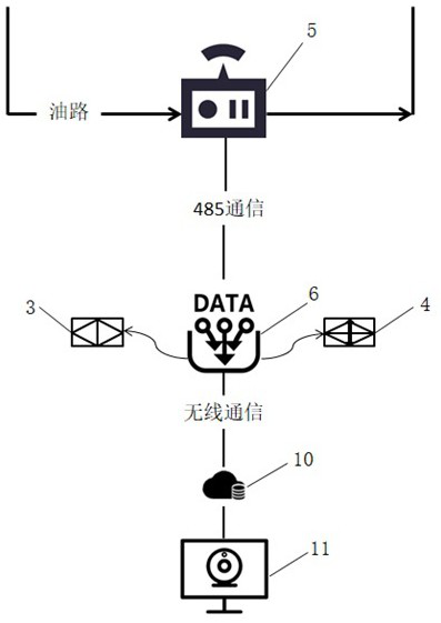
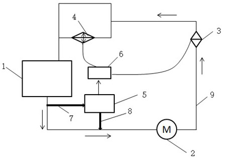
[0050] Such as figure 1 As shown, the online monitoring device for lubricating oil of a wind turbine gearbox provided in this embodiment includes a lubricating oil bypass 12 for leading out the oil in the main oil circuit 9 of the hydraulic system of the gearbox 1 to provide an interface for the online monitoring device 5 The online monitoring device 5 is used to monitor various parameters of the lubricating oil in real time, including lubricating oil temperature, density, viscosity, water content, water activity, dielectric constant, particle size; the data transmission and control module 6 is used for communication and Control, collect the monitoring data transmitted by the online monitoring device 5, and upload it to the cloud server 10 through wireless communication, and then start related control operations according to the administrator and the established program; the cloud server 10 is used to store system preset information and data A large amount of continuous monito...
Embodiment 2
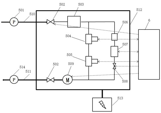
[0054] Such as image 3 , as a specific preferred implementation, the online monitoring device 5 includes an inlet pressure gauge 501, an inlet solenoid valve 502, a defoaming module 503, an oil sensor 504, a moisture sensor 505, a pressure-stabilizing buffer tank 506, a particle size sensor 507, Flow regulating valve 508, circulating pump 509, oil inlet 510, oil outlet 511, housing 512, power supply module 513, outlet pressure gauge 514, outlet solenoid valve 515, first monitoring pipe 516, second monitoring pipe 517.
[0055] Wherein, the inlet pressure gauge 501 and the outlet pressure gauge 514 are respectively installed in front of the oil inlet 510 and behind the oil outlet 511, and are arranged outside the housing 512 to detect the oil inlet and the oil outlet pipeline of the online monitoring device. pressure; the inlet electromagnetic valve 502 is installed behind the oil inlet 510 and before the defoaming module 503, and is used to control the opening and closing of ...
Embodiment 3
[0059] Such as Figure 4, as a specific preferred implementation, the data transmission and control module 6 includes an RS485 communication unit 603, a wireless communication unit 602, a first control unit 601, and a second control unit 604; wherein the RS485 communication unit 603 and the online monitoring device 5 connected; the wireless communication unit 602 includes a 4G communication module or a wifi communication module, and uploads the monitoring data to the cloud server 10; the first control unit 601 is connected to the oil filter 3 and the oil cooler 4 respectively; The second control unit 604 is respectively connected with the inlet solenoid valve 502, the outlet solenoid valve 515, the flow regulating valve 508, and the circulation pump 509; the monitoring and control functions are parallel, so that the detection results can be used to achieve rapid data integration and storage, and high-efficiency Two-way information transmission, confidentiality and security, su...
PUM
 Abstract
Description
Claims
Application Information
 - R&D
- Intellectual Property
- Life Sciences
- Materials
- Tech Scout
- Unparalleled Data Quality
- Higher Quality Content
- 60% Fewer Hallucinations
Browse by: Latest US Patents, China's latest patents, Technical Efficacy Thesaurus, Application Domain, Technology Topic, Popular Technical Reports.
© 2025 PatSnap. All rights reserved.Legal|Privacy policy|Modern Slavery Act Transparency Statement|Sitemap|About US| Contact US: help@patsnap.com


