Seal structure for relatively rotational members

a technology of relative rotation and sealing structure, which is applied in the direction of mechanical actuated clutches, couplings, roads, etc., can solve the problems of difficult to structure an entire coupling structure in a compact configuration, the proportion between the seal member and the housing is easily worn, and the difficulty of reducing the peripheral speed, so as to improve the sealing ability and reduce the peripheral speed

Inactive Publication Date: 2006-06-20
TOCHIGI FUJI IND CO LTD
View PDF8 Cites 14 Cited by
  • Summary
  • Abstract
  • Description
  • Claims
  • Application Information

AI Technical Summary

Benefits of technology

[0017]Further, selecting the sliding radius of curvature of the seal member to be in a small value enables a peripheral speed to be decreased with a resultant further improvement in the sealing capability.

Problems solved by technology

But, in a case where the housing, that forms the rotary member, is made of aluminum alloy (light metal), the aluminum alloy has a low hardness to cause a sliding portion between the seal member and the housing to be easily worn, resulting in an issue of an inability of easily determining the sliding portion.
Further, while another proposal has been made in the past to provide the dust cover to improve an effectiveness for preventing entry of foreign material, it has been a usual practice to have the dust cover and the seal member to be located at separate positions to need separate mounting spaces, causing a difficulty in structuring an entire structure of the coupling in a compact configuration.

Method used


Image

  • Seal structure for relatively rotational members
  • Seal structure for relatively rotational members
  • Seal structure for relatively rotational members

Examples


first embodiment

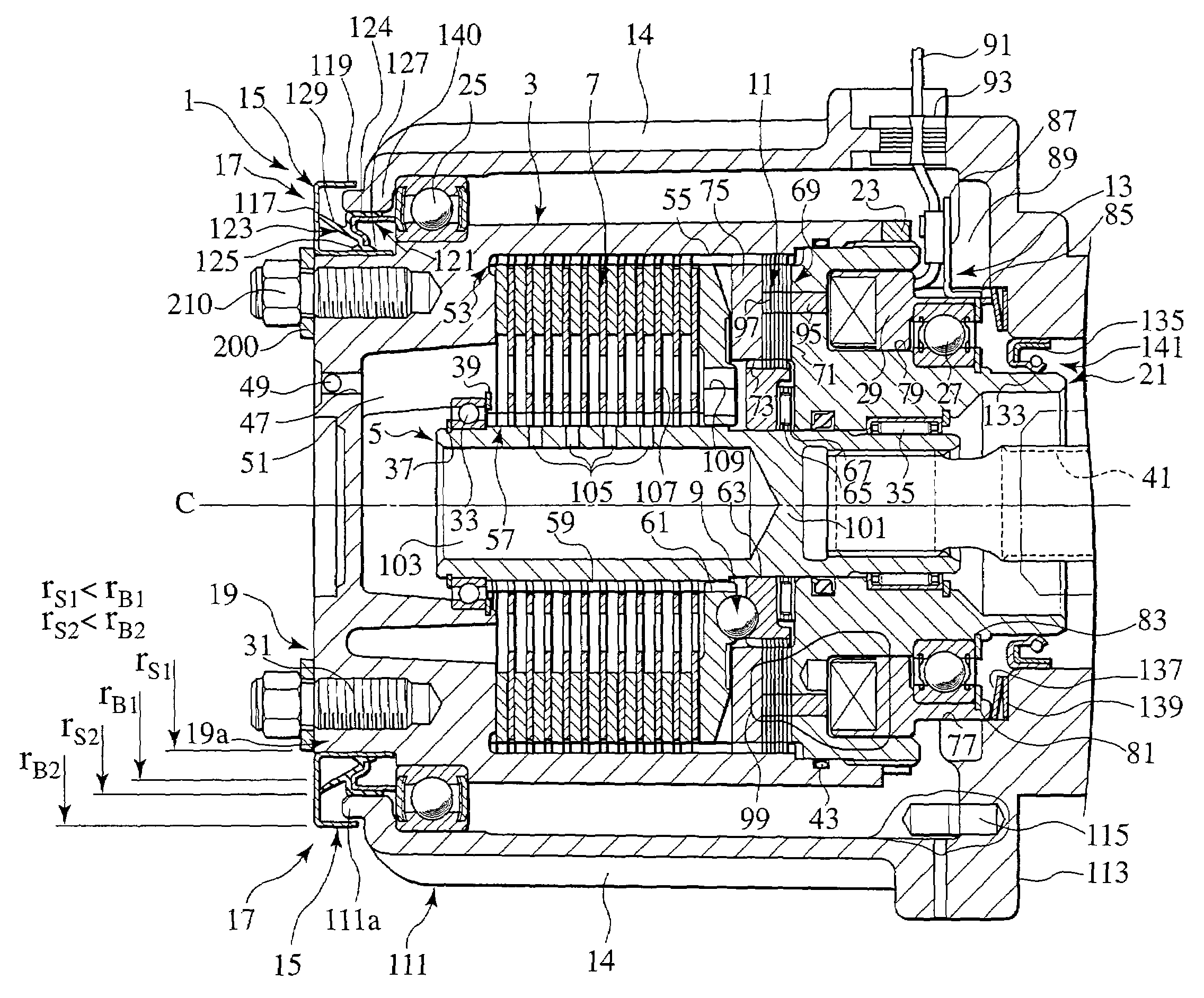
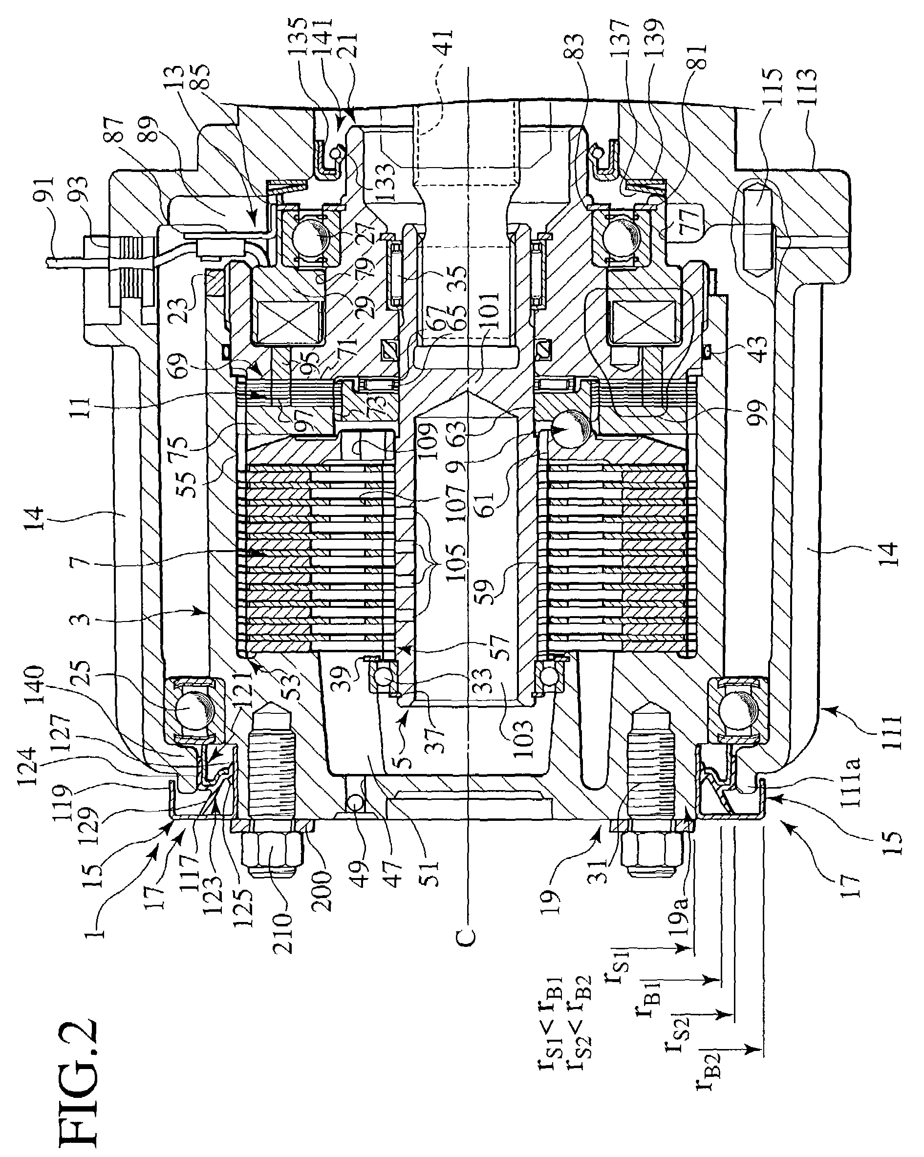
[0083]The seal member 17 is comprised of a retaining fixture (retaining member) 121 and a seal member 123 that is integrally formed with a plurality of (three pieces in the first embodiment) lips 125, 127, 129.

[0084]The retaining fixture 121 is press fitted to the fore end 111a of the front housing 111 by means of a base portion 124 of the seal member 123. Such a press fitted portion may be additionally applied with sealing material. Also, the lips 127, 129 are held in sliding contact with the dust cover 15. In particular, the lip 127 is held in sliding contact with a thrust surface 150 extending from a dust cover 15 concentric with a rotational axis of the cylindrical member 19, and an annular sliding portion is formed between the thrust surface 150 and the seal portion 123. Also, the lip 129 is held in sliding contact with a radial surface (side wall) 117 of the dust cover 15 concentric with the rotational axis of the cylindrical member 19, and an annular sliding portion is formed...

third embodiment

[0152]According to this embodiment, the seal structure has, in addition to the effects of the third embodiment, an improved strength of the sliding portion while enabling the corrosion resistant property, the heat-resistant property and the anti-wearing property to be further improved.

[0153]Also, the surface hardening treatment involves heat treatment such as tempering / quenching or carbonizing and anode oxidizing treatment and, in addition to these treatments, further involves PTFE coating providing a self-lubricating property, nickel dispersion plating, chrome plating and electroless nickel plating.

[0154]Further, a stepped portion 200c formed between adjacent treated surfaces 200a, 200b, which are subjected to surface hardening treatment, of the fore end 19a of the cylindrical member 19 such that the stepped portion 200c permits the dust cover 15e to be positioned at one side of the rotational axis of the cylindrical member 19.

[0155]FIG. 8 is an enlarged cross sectional view illust...


PUM


Abstract

A seal structure is disclosed as mounted in a coupling 1, exposed in the vicinity of a stationary member 14, with a dust cover 15 being mounted to a cylindrical member 19 for preventing foreign material from entering a gap between the coupling 1 and the stationary member 14, and a seal member 17 is disposed at a position opposed to the dust cover on the stationary member 14, with a seal portion 123 of the seal 17 being held in sliding contact with the dust cover 15.

Description

BACKGROUND OF THE INVENTION[0001]The present invention relates to a seal structure for relatively rotational members to be employed between a rotary member, such as a coupling exposed to and connected to a propeller shaft of a four-wheel drive vehicle, and a stationary member that retains the rotary member to a vehicle body.[0002]In general, attempts have heretofore been made to propose structures as disclosed in Japanese Patent Application Laid-open No. 1-182633 and 10-292827 wherein a coupling (rotary member) is exposed to and connected to a propeller shaft of a four-wheel drive vehicle and wherein a rotary member is exposed outside and located in the vicinity of a stationary member. With the structure wherein the rotary member is exposed outside and located, as shown in Japanese Patent Application Laid-open No. 10-292827, an attempt has been made to dispose a seal structure, such as a dust cover or seal members, between the rotary member and the stationary member to prevent forei...

Claims


Application Information

Patent Timeline
Patent Type & Authority Patents(United States)
IPC IPC(8): F16D27/115F16J15/32F16C33/72F16C33/76
CPCF16C33/76F16C33/805F16J15/3264F16D27/115Y02T10/76F16D27/004F16D2300/08
Inventor YOSHIDA, SHOUJI
Owner TOCHIGI FUJI IND CO LTD
Why Eureka
Try Eureka