[0020]By utilizing well-known
filament winding techniques, the material properties of each tube can be specifically tailored to react localized stresses generated from the application of external forces upon the structure. In general, a triangular tube is formed with multiple
layers or “plies” of
composite material having fibers aligned in different directions. The plies of
composite material are arranged with respect to one another to provide a
structural element which is capable of reacting to forces in multiple directions. By utilizing alternate plies of fibers oriented at between 0° and 90° orientations relative to the longitudinal axis of the structure, each individual tube will be capable of reacting tensile, compression and
shear stress from multiple directions. It will be appreciated that by tailoring the load carry capability of the individual tubes to suit the loads they are expected to encounter, a lightweight, efficient, load carrying structure may be produced.
[0021]It is also envisioned that the skins surrounding the internal and external surfaces of the shell and internal support member may be formed with filament wound
fiber composite material. Like the construction of the individual triangular tubes discussed above,
filament winding techniques may be utilized to tailor the load carrying properties of the
skin. By providing
layers of composite material having fibers running parallel to the longitudinal axis of the structure, skins suited for carrying localized stresses resulting from the application of longitudinal bending loads may be produced. Likewise, by incorporating
layers of composite material having fibers oriented at between 0° and 90° to the longitudinal direction, the skins may also have the ability to react shear stresses resulting from torsional loading of the structure.
[0022]In order to design and fabricate integrally stiffened load carrying composite structures embodying the present invention, an
estimation of the external forces which will be reacted by the proposed structure must be determined. This
estimation requires a thorough understanding of the loading environment and operating conditions that the proposed design is expected to experience. Based upon these expected loading characteristics, the geometry of the proposed design can be used to resolve these forces and moments into resulting localized stresses. Individual structural components can then be appropriately sized and designed to efficiently carry these expected stresses.
[0023]Once the localized stresses are known, individual components which form the load carrying structure can be fabricated. The process of building up individual
fiber reinforced skins and tubular elements is essentially a three-dimensional strengthening process. By utilizing
filament winding techniques, fibers pre-impregnated with matrix material are wound under controlled tension to thereby precisely arrange multiple layers of fiber on a shaped mandrel surface.
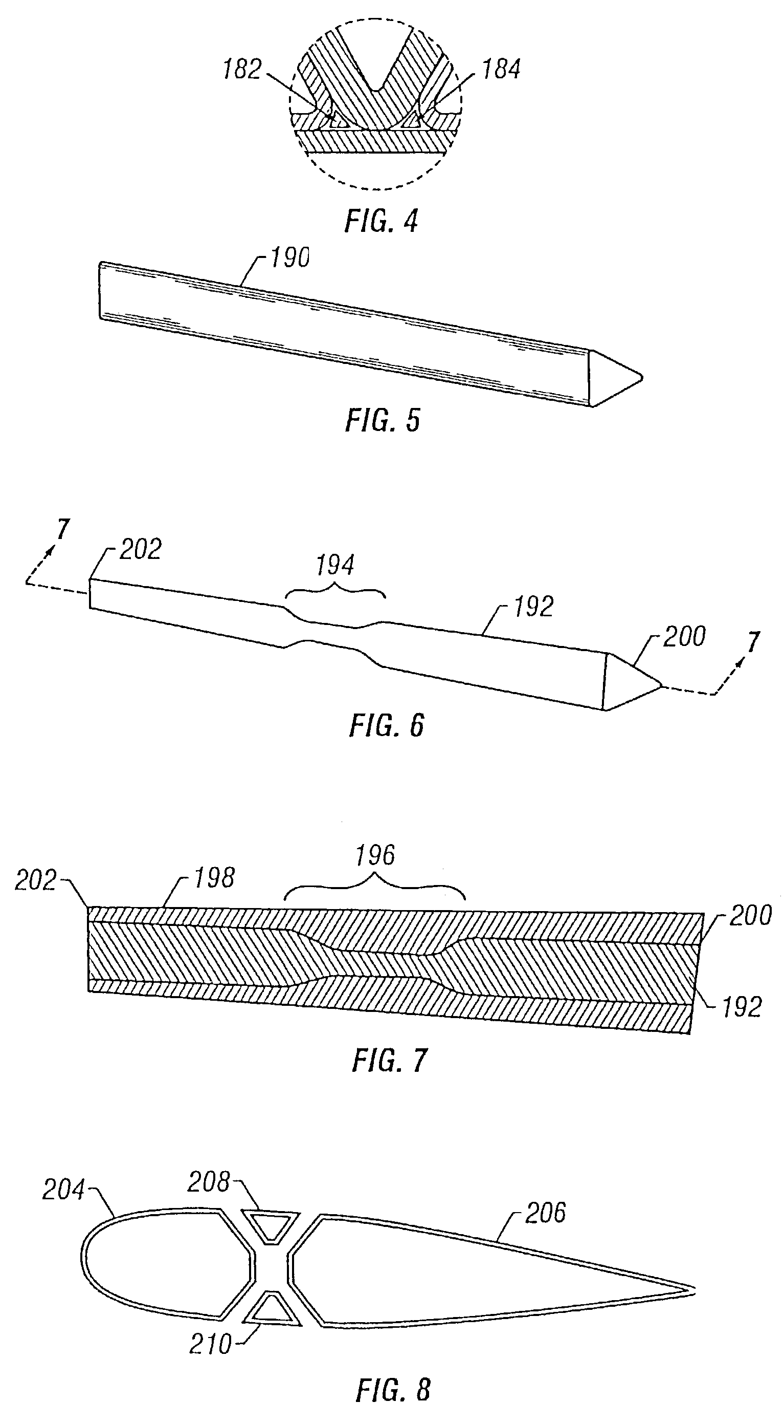
[0025]After the individual triangular mandrels have been wound with an appropriate combination of fiber, they are placed together side-by-side in a geometrically complimentary fashion about appropriately shaped pre-wound mandrels to form the load carrying structure having a predetermined external contour. Additional fiber is then wound about the exterior of the
assembly to provide a
skin surrounding the exterior surface of the structure. The
assembly is then placed into a mold having mold faces shaped to desired external contour of the structure. For most applications, this process eliminates the need for vacuum bagging and autoclaves.
Temperature and pressure are employed by the mold to cure the composite, thereby bonding the skins and triangular tubes together. After the structure has cured, the individual mandrels are removed from the structure to provide an integrally formed, unitary load carrying body.
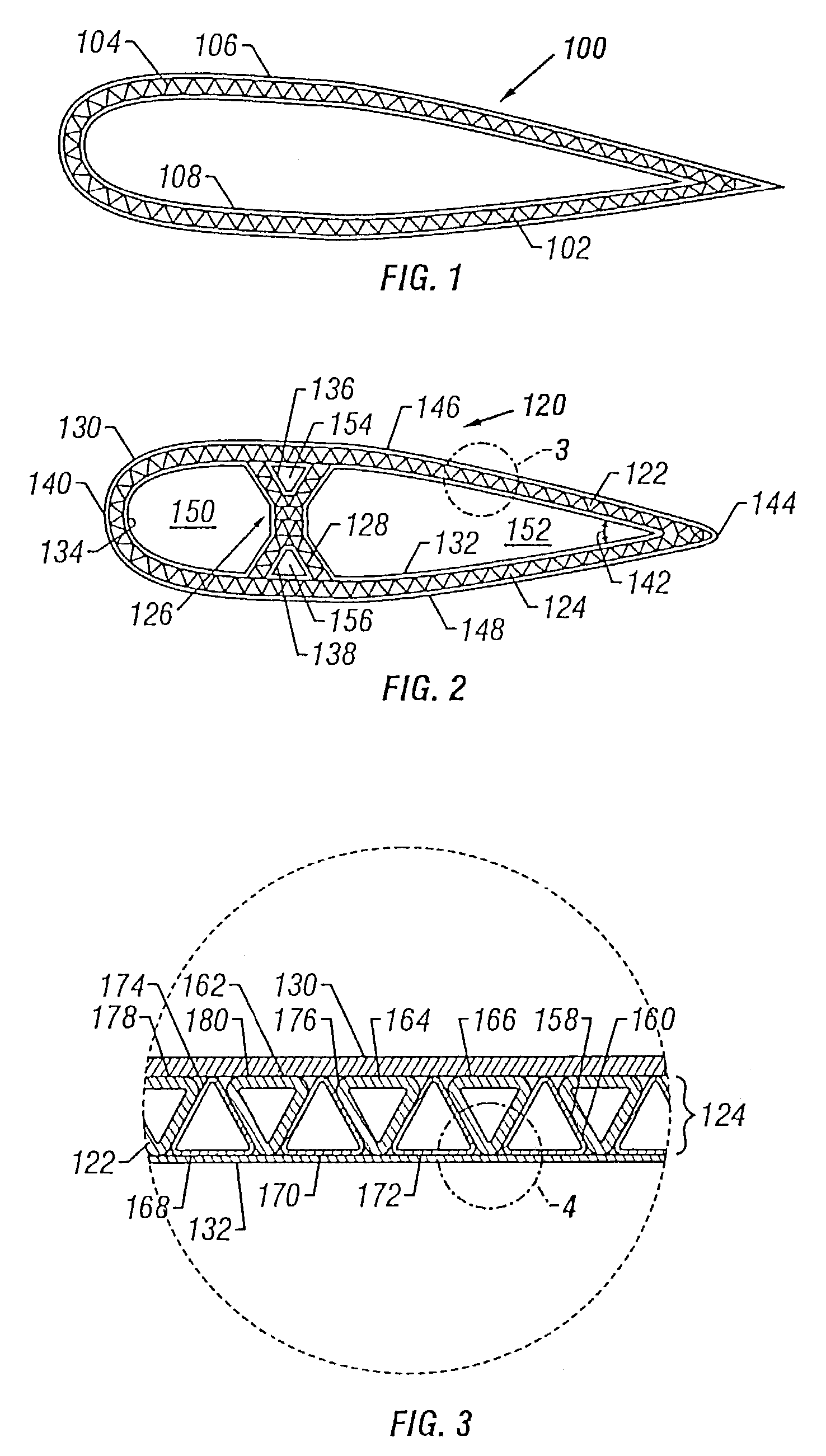
[0026]It will be appreciated that, by way of example and not of limitation, the present invention is capable of providing integrally stiffened aircraft wing structures, rotor blades,
fuselage segments and the like, having a reinforced load carrying shell formed integral to an underlying support member, such as an X-shaped spar or strut. The
skin, reinforced, shell and underlying internal support member thereby cooperate to carry static and aerodynamic forces encountered all aspects of aircraft operation. As a result of this novel method of construction, the need for individual stringers, ribs, spars, and skin sections typically used in combination to form conventional aircraft structures is eliminated.

