Mask ROM and fabrication thereof

Inactive Publication Date: 2006-06-20
MACRONIX INT CO LTD
View PDF9 Cites 0 Cited by
  • Summary
  • Abstract
  • Description
  • Claims
  • Application Information

AI Technical Summary

Benefits of technology

[0009]Accordingly, this invention provides a Mask ROM and the fabrication thereof to prevent diffusion of the implanted coding dopants into the buried bit lines and thereby avoid the current in the buried bit lines from decreasing.
[0010]This invention also provides a Mask ROM and the fabrication thereof to improve the coding accuracy without using phase shift masks (PSM) or optical proximity correction (OPC), so as to reduce the cost for fabricating the photo mask.
[0014]Accordingly, this invention is capable of increasing the margin of the Mask ROM coding process.

Problems solved by technology

However, since the coding windows do not distribute evenly and there must be some regions with dense coding window patterns (dense regions) and some with isolated coding window patterns (sparse regions) on the coding photo mask, the critical dimensions (CD) of the coding windows are not uniform.
The CD deviations of coding windows cause misalignments of the coding implantation, which may results in severe coding errors to lower the reliability of the Mask ROM product.
However, the two methods both need to design special patterns on the photo masks, so the fabrication of the photo masks are time-consuming, expensive and difficult.
Moreover, it is not easy to debug the patterns on such a photo mask after the photo mask is fabricated.

Method used


Image

  • Mask ROM and fabrication thereof
  • Mask ROM and fabrication thereof
  • Mask ROM and fabrication thereof

Examples


Embodiment Construction

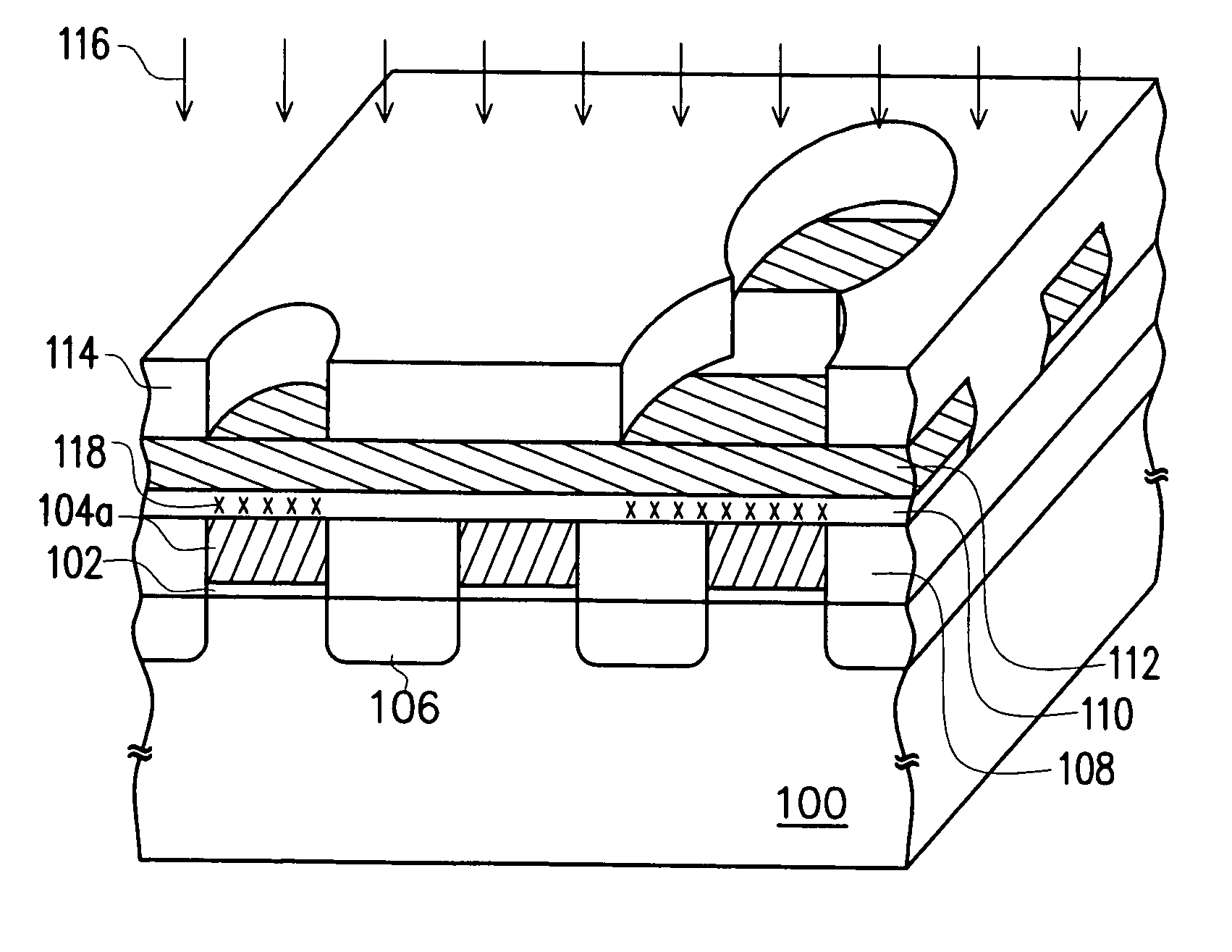
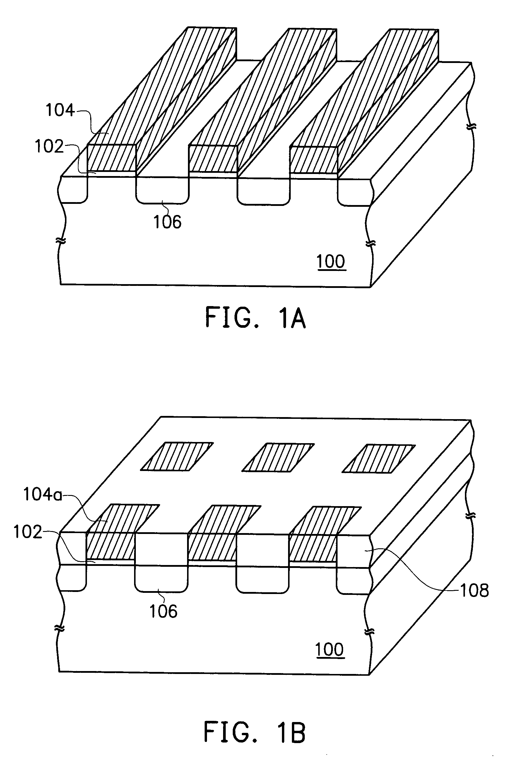
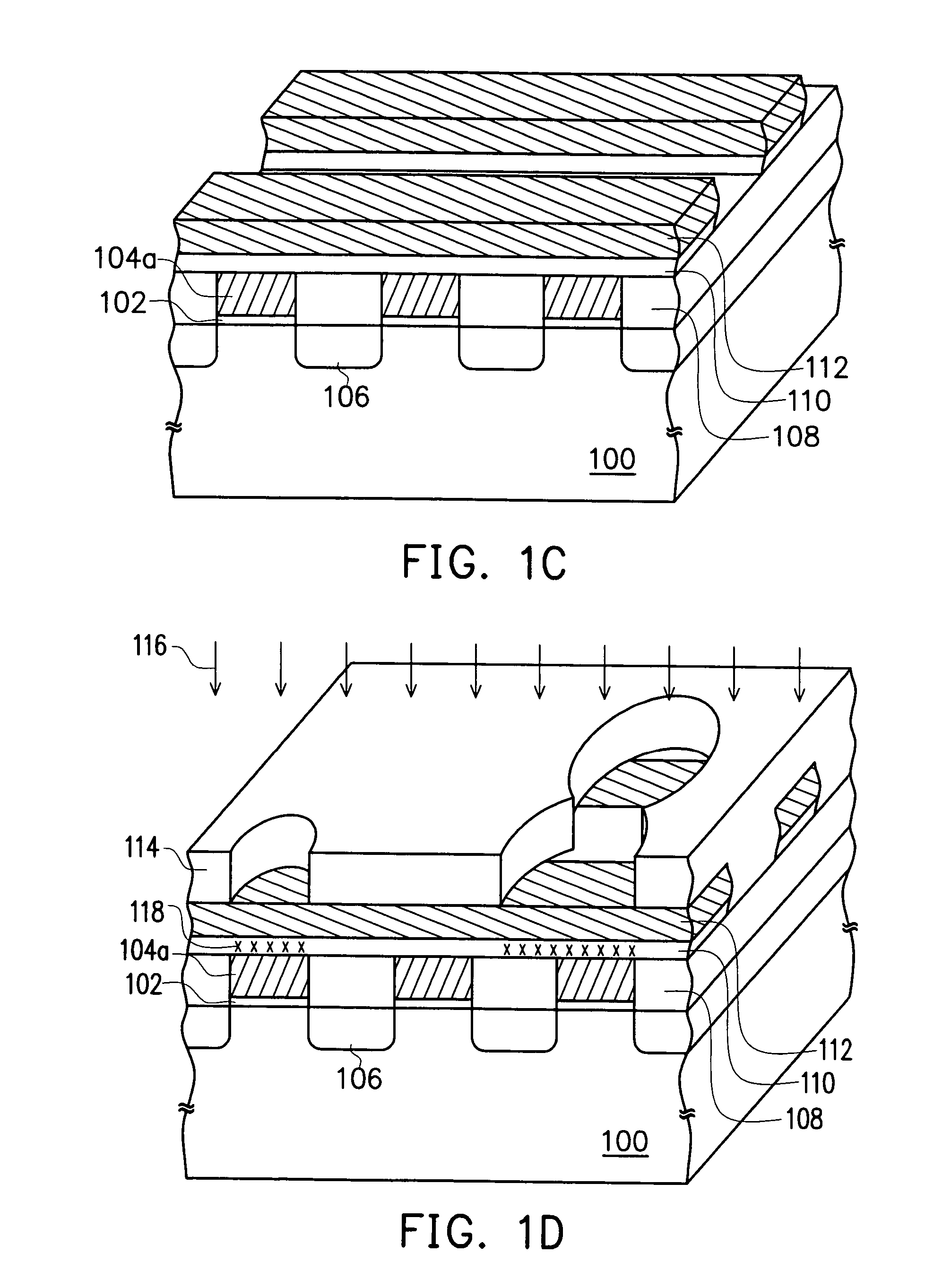
[0018]FIG. 1A˜1D illustrate a process flow of fabricating a Mask ROM according to a preferred embodiment of this invention in a perspective view.

[0019]Refer to FIG. 1A, a substrate 100 is provided, and then a gate oxide layer 102 and a plurality of strip conductive structures 104 are formed on the substrate 100, wherein the strip conductive structures 104 comprise a material such as polysilicon. The method for forming the gate oxide layer 102 and the strip conductive structures 104 may be the one described below. A thin oxide layer (not shown) and a conductive layer (not shown) are sequentially formed on the substrate 100, and then the conductive layer and the thin oxide layer are patterned into the strip conductive structures 104 and the gate oxide layer 102, respectively.

[0020]Thereafter, an ion implantation is performed using the strip conductive structures 104 as a mask to form a plurality of buried bit lines 106 in the substrate 100 between the strip conductive structures 104.

[...


PUM


Abstract

A Mask ROM and a method for fabricating the same are described. The Mask ROM comprises a substrate, a plurality of gates on the substrate, a gate oxide layer between the gates and the substrate, a plurality of buried bit lines in the substrate between the gates, an insulator on the buried bit lines and between the gates, a plurality of word lines each disposed over a row of gates perpendicular to the buried bit lines, and a coding layer between the word lines and the gates.

Description

CROSS-REFERENCE TO RELATED APPLICATION[0001]This application is a divisional application of, and claims the priority benefit of, U.S. application Ser. No. 10 / 065,645 filed on Nov. 05, 2002 now U.S. Pat. No. 6,777,762.BACKGROUND OF THE INVENTION[0002]1. Field of Invention[0003]The present invention relates to a memory structure and a method for fabricating the same. More particularly, the present invention relates to a structure of a mask programmable read-only memory (Mask ROM) and a method for fabricating the same.[0004]2. Description of Related Art[0005]A Mask ROM generally comprises a substrate, a plurality of buried bit lines in the substrate and a plurality of word lines crossing over the buried bit lines, wherein the substrate under the word lines and between the buried bit lines serves as the channel regions of the memory cells. A method for programming a Mask ROM comprises implanting ions into the channel regions of selected memory cells to raise their threshold voltages, wh...

Claims


Application Information

Patent Timeline
IPC IPC(8): H01L21/8236H01L21/8246H01L27/112
CPCH01L27/1124H01L27/112H10B20/363H10B20/00
Inventor CHANG, CHING-YU
Owner MACRONIX INT CO LTD
Why Eureka
Try Eureka