
Ring switching method and node apparatus using the same

Inactive Publication Date: 2006-06-20
FUJITSU LTD
View PDF3 Cites 55 Cited by
  • Summary
  • Abstract
  • Description
  • Claims
  • Application Information

AI Technical Summary

Benefits of technology

[0009]An object of the present invention is to provide an improved ring switching method and apparatus in which the above-described problems are eliminated.
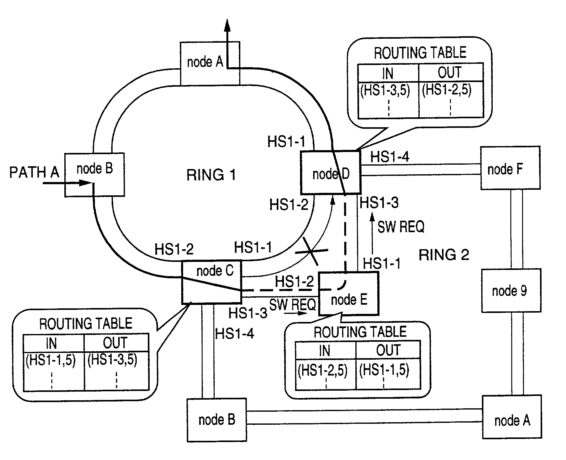
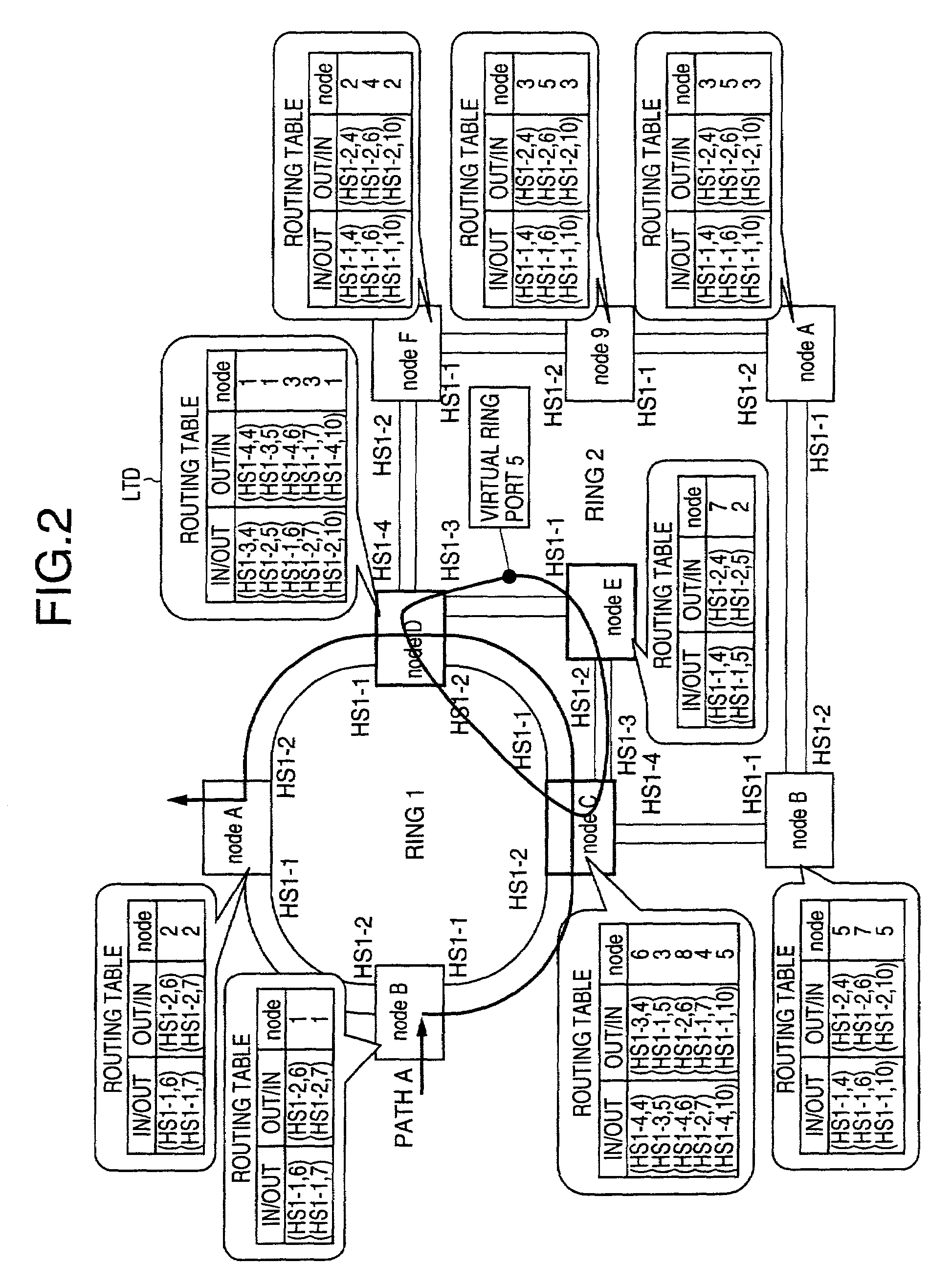
[0010]Another object of the present invention is to provide a ring switching method that can determine, at the time of detection of a failure, a bypass route among virtual ring routes suited to the network configuration, in order to compensate for the transmission over the ring network, and can lower the ratio of the protection channels to the working channels.
[0011]Another object of the present invention is to provide a node apparatus that that can determine, at the time of detection of a failure, a bypass route among virtual ring routes suited to the network configuration, in order to compensate for the transmission over the ring network, and can lower the ratio of the protection channels to the working channels.
[0014]According to the ring switching method and node apparatus of the present invention, it is possible to determine a bypass route among virtual ring bypass routes suited to the network configuration, in order to compensate for the transmission over the network at the time of detection of a failure. It is possible for the present invention to lower the ratio of the protection channels to the working channels. Further, according to the ring switching method and node apparatus of the present invention, it is possible to avoid the deactivation of all the PCA circuits of the ring network in the opposite direction at the time of detection of a failure.

Problems solved by technology

However, the above-mentioned BLSR method treats the protection channels in a fixed manner, and the ratio of the protection channels to the working channels is relatively large.
Even when another bypass route passing through different rings exists in the network, the conventional method does not serve to effectively use the protection channels of such another bypass route.
It is difficult for the conventional method to avoid the cut-off of the transmission when a multiple failure occurs in the ring to which the node apparatus itself pertains.
The conventional method has a problem in that, even when only one working channel is used on the line where the failure is detected, all the PCA circuits of the ring in the opposite direction will be deactivated due to the failure.

Method used


Image

  • Ring switching method and node apparatus using the same
  • Ring switching method and node apparatus using the same
  • Ring switching method and node apparatus using the same

Examples


Embodiment Construction

[0028]A description will now be given of preferred embodiments of the present invention with reference to the accompanying drawings.

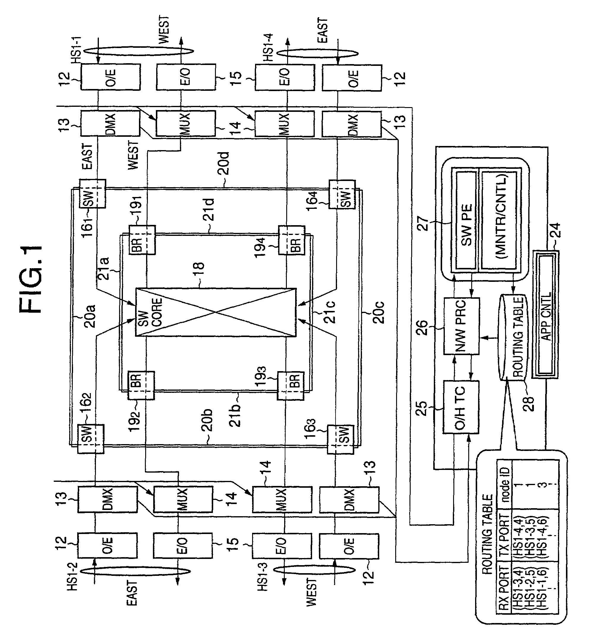
[0029]FIG. 1 shows one embodiment of the node apparatus in which the ring switching method of the present invention is incorporated for use in a ring network.

[0030]As shown in FIG. 1, with respect to each of transmission lines HS 1-1, HS 1-2, HS 1-3 and HS 1-4, the node apparatus of the present embodiment includes an opto-electrical conversion circuit (O / E) 12, a demultiplexer (DMX) 13, a multiplexer (MUX) 14, and an electro-optical conversion circuit (E / O) 15. The opto-electrical conversion circuit 12 receives an incoming optical signal from the related transmission line, and provides opto-electrical conversion of the received signal to generate an electric signal. The demultiplexer 13 separates the multiplexed signal sent by the O / E 12, into electrical signals. The multiplexer 14 provides multiplexing of transmitting signals. The electro-optical conve...


PUM


Abstract

A node apparatus for a ring network arranged in a multi-ring formation includes a routing table that defines relationships between a receiving physical line identifier with port number and a sending physical line identifier with port number for virtual ring bypass routes, the relationships being individually provided for respective transmission lines connected to the node apparatus. A detection unit detects, at a time of detection of a failure, each of the relationships from the routing table to determine a transmission line to which a switching request is sent. The detection unit detects, at a time of relaying, each of the relationships from the routing table to determine a transmission line to which one of a switching request and a switching response is sent. The detection unit detects, at a time of receiving of a switching request, each of the relationships from the routing table to determine a transmission line to which a switching response is sent.

Description

BACKGROUND OF THE INVENTION[0001]1. Field of the Invention[0002]The present invention relates to a ring switching method that determines a bypass route in a multi-ring network in order to recover the transmission against a failure in the network. Moreover, the present invention relates a node apparatus that performs the ring switching method.[0003]2. Description of the Related Art[0004]Conventionally, when a ring network is constituted by a plurality of SONET (Synchronous Optical Network) devices and a recovery of the transmission over the network against a failure is needed, the BLSR (Bidirectional Line Switched Ring) switch operation is performed in conformity with the GR-1230-CORE of Telcordia Technologies. In this requirement, it is specified that a failure switching request, which is carried by the APS (k1, k2) bytes of the overhead of SONET frame, is notified to a far-end node of the network, and that software switch operation be performed in order to bypass the failure-detect...

Claims


Application Information

Patent Timeline
IPC IPC(8): G01R31/08H04B10/03H04B10/032H04B10/07H04B10/275H04J3/08H04L12/437H04Q11/04
CPCH04J3/085H04J2203/0042H04J2203/0066H04J2203/006H04J2203/0053
Inventor NAGAMINE, KAZUAKI
Owner FUJITSU LTD
Learn More