Magnetic marker for manufacturing processes and identification of finished workpieces

Inactive Publication Date: 2006-06-27
DANKO DONALD M +1
View PDF7 Cites 19 Cited by
  • Summary
  • Abstract
  • Description
  • Claims
  • Application Information

AI Technical Summary

Benefits of technology

[0027]When in use, the invention provides a method of efficiently producing heavy duty U-bolts of different sizes, wherein each U-bolt has two legs of substantially equal length. The method includes the steps of providing a supply of straight metal rods with opposite ends, smooth cylindrical outer surfaces, different predetermined lengths, and transverse center planes defining a longitudinal center of each rod substantially equidistant from the ends of each rod. Helical threads are formed on opposite end portions of each rod, which are successively

Problems solved by technology

Still more time is wasted in determining the longitudinal center of the rod, and then positioning it ov

Method used


Image

  • Magnetic marker for manufacturing processes and identification of finished workpieces
  • Magnetic marker for manufacturing processes and identification of finished workpieces
  • Magnetic marker for manufacturing processes and identification of finished workpieces

Examples


Embodiment Construction

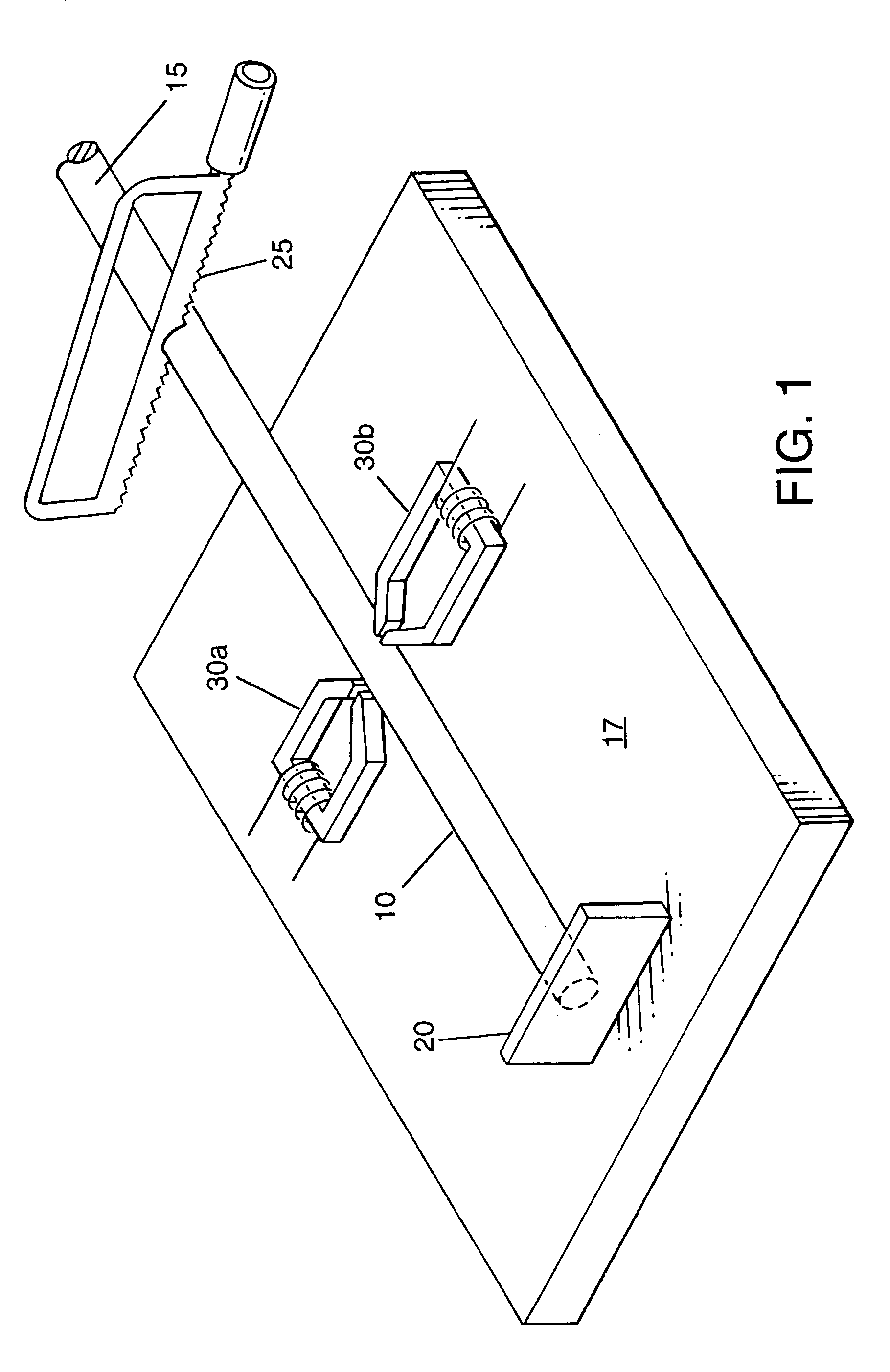
[0052]Referring to FIG. 1, the cylindrical metal rod 10 is shown being cut to the desired length, from the metal rod stock 15. The rod stock 15, stabilized on a table, workbench or support frame 17, is inserted longitudinally into the cutoff station until it reaches the end stop 20. Two magnetizing heads 30a and 30b, each bearing a coil 30, are placed on either side of the inserted cylindrical rod stock 15 at its midpoint, where it is magnetically marked by passing a momentary pulse of DC current through the coil of the magnetizing heads. Upon completion of magnetically marking the longitudinal center of the metal rod, it is cut to the desired length using cutoff saw 25.

[0053]The straight metal rod 10 is commonly manufactured in a wide range of diameters that range from ¼ inch to 1¼ inches. Depending upon the application, the material composition that is used for the U-bolts can be of a mild steel.

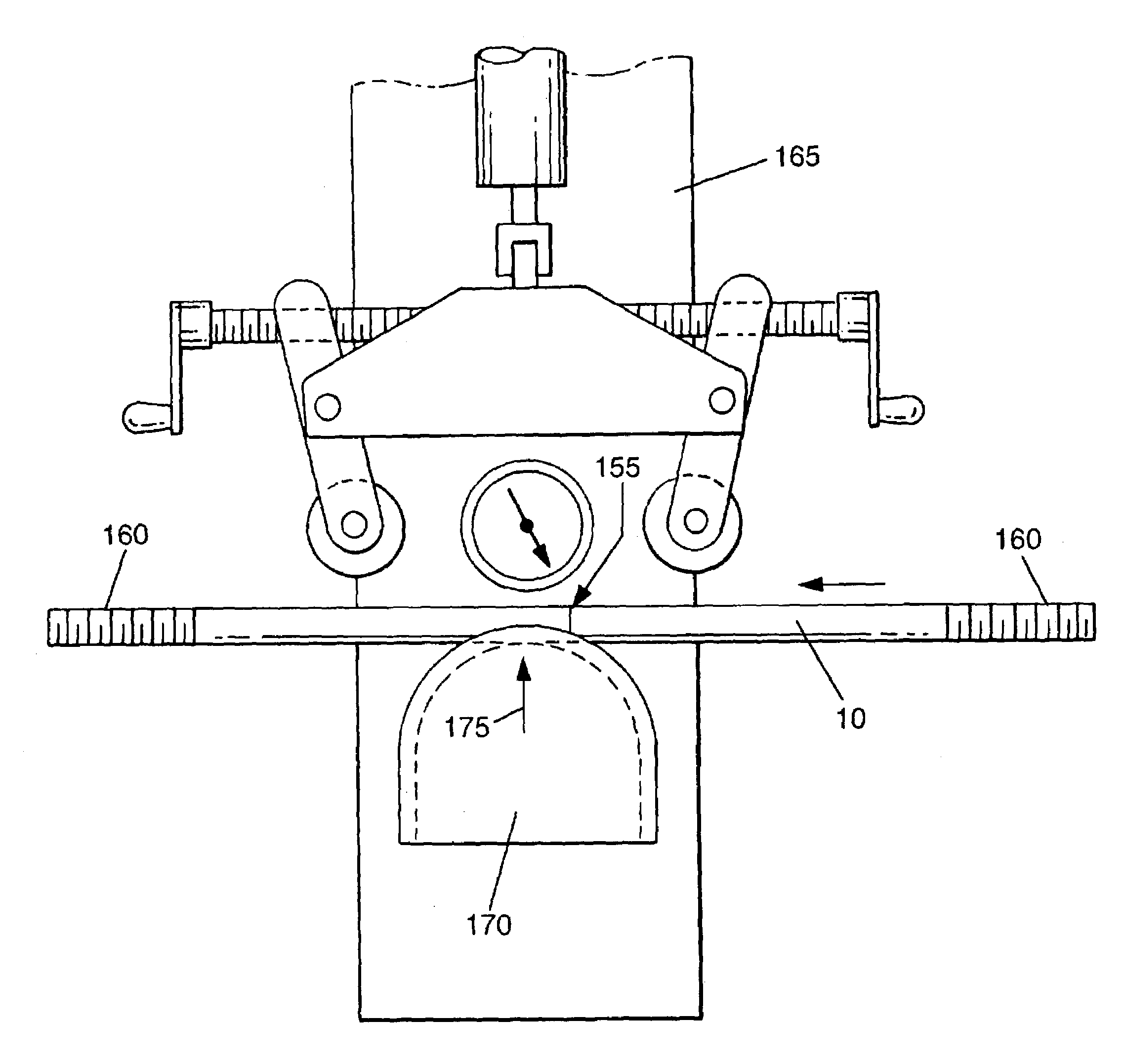
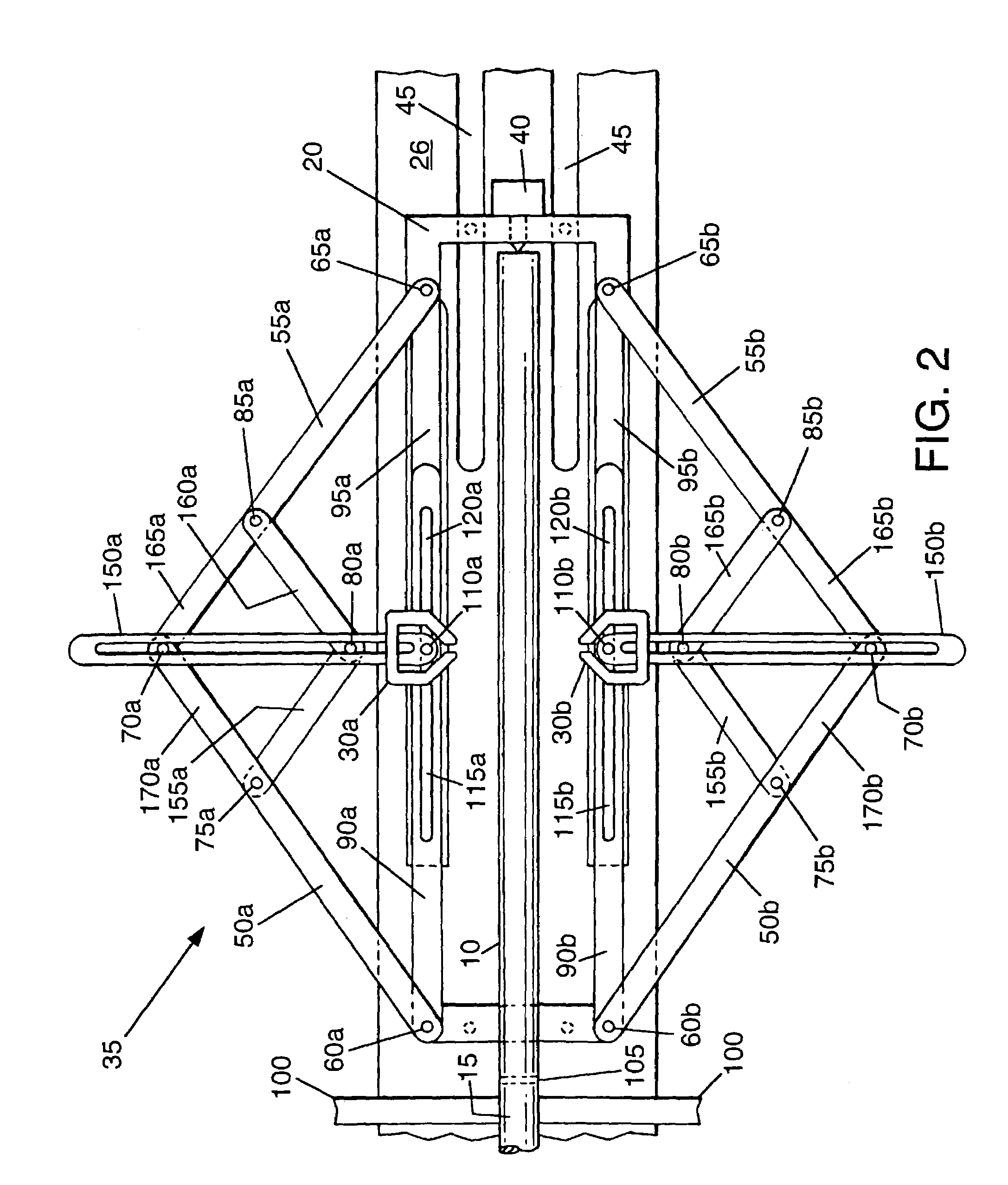
[0054]To provide an automated means of finding the midpoint of the cylindrical rod po...


PUM

PropertyMeasurementUnit
Electric potential / voltageaaaaaaaaaa
Polarityaaaaaaaaaa

Abstract

A permanent invisible magnetic marking and positioning system of unfinished steel rods, spring steel bars, workpieces, and the like. A midpoint or center of the rod, bar or workpiece is automatically located and a high-energy pulse is applied for an embedded magnetic marker in the workpiece. Meanwhile, the magnetizing heads can also be repositioned to various points on a workpiece for imparting manufacturing and product identification data. In the case of leaf springs, the center of a spring steel bar is located a magnetic marker is embedded there. A high-energy rectangular pulse imparts a permanent invisible magnetic marks and data. The embedded indicators having peak magnetic strength allow manual or automatic positioning for perfect alignment in bending, tapping and other forming processes.

Description

[0001]Applicants claim the benefit of domestic application which is a continuation-in-part of Ser. No. 09 / 696,618, filed Oct. 25, 2000, U.S. Pat. No. 6,526,793, issued Mar. 4, 2003.FIELD OF THE INVENTION[0002]The present invention relates primarily to a permanent magnetic marking and positioning system of unfinished metal bars, workpieces and the like, and more particularly, to a magnetic marking and positioning system, which permits central alignment of a cylindrical steel rod, a flat bar or other workpiece to its longitudinal center or other designated point prior to a bending, tapping or another manufactured formation.BACKGROUND OF THE INVENTION[0003]In the manufacture of U-bolts, springs and other related parts, it is common to cut a long steel rod or bar into shorter sections of predetermined length. For U-bolts, each rod section remains straight and each is threaded along the opposite end portions. To produce a U-bolt, each of the threaded straight rods are then successively i...

Claims


Application Information

Patent Timeline
IPC IPC(8): G01N3/00G01B7/04G01R33/12B25H7/04G01B7/00G01B7/02G01D5/20
CPCB25H7/04G01D5/2033G01B7/023G01B7/003Y10T83/4458Y10T83/541
Inventor DANKO, DONALD M.TADDEO, JOSEPH H.
Owner DANKO DONALD M
Why Eureka
Try Eureka