Continuous rotary hole punching method and apparatus

a continuous rotary and hole punching technology, applied in the field of method and apparatus for punching holes in deformable strips, can solve the problems of insufficient or no waste ejection, low production speed, and existing methods for punching material strips, and achieve the effect of positive ejection of waste materials

Active Publication Date: 2006-06-27
TBS USA INC
View PDF13 Cites 9 Cited by
  • Summary
  • Abstract
  • Description
  • Claims
  • Application Information

AI Technical Summary

Benefits of technology

[0013]The method and apparatus of the present invention substantially overcomes the problems of the prior art and permits continuous, high-speed production of punched strip having an array of high-tolerance closely-spaced holes with positive ejection of waste material.
[0021]The continuous indexing of the strip can be accredited to the second shaft having the male / female die which plays three roles throughout the grid production. First, it functions as a male die, punching the set of first rows of spaced-apart holes into the strip against the first shaft, acting as the female die. Second, the male dies proceed to index the material using the male dies which are snugly positioned in the rows of holes punched in the first step. Third, the second shaft acts as a female die, and allows another toolset, on shaft three, to accurately punch the second set of rows of holes into the spaces between the first set of rows of holes. The result is a continuous array of accurately punched closely spaced holes in a continuous grid of the constituent deformable material.

Problems solved by technology

Existing methods for punching material strips incur problems including low production speed, inadequate or no waste ejection, insufficient indexing precision, hole size and spacing tolerance errors, and the distortion or destruction of the final product.
These mechanically moving parts must be sufficiently robust to endure cycling, but for small, closely spaced holes there is insufficient space on a shaft for any sort of ejection mechanism, robust or otherwise.
Thus, these systems have been difficult to implement and to adapt for the punching of closely spaced holes.
However, the problem of indexing the material to be punched from one set of tooling to the next, without compromising hole size and spacing tolerances persisted.
As a result, there were frequent issues with subsequent holes not being placed the appropriate distance from the first set of holes and tolerance errors accumulated.
However, not only did the punched material not eject, but the finished product was reluctant to peel from between the male dies.
Mesh had to be forcefully stripped from the male dies, which ruined the final product.
Also, the entrapped waste would build up in the holes on the female shaft and cause the mechanism to seize, resulting in broken tooling.
This paper also states “Products with many rows of holes, in particular in combination with close hole spacings in feed direction, can only be manufactured by rotary blanking at great expense.
On the other hand, the number of punches, which rises with the roller diameter and the number of rows, lets maintenance of the tools become very costly.
This segmented approach is production-rate limiting and is relatively slow compared to rotary punching because the process is stop-and-go as opposed to continuous.
These reciprocating punch presses must be robust and powerful to punch metal and the constant change in momentum due to machine oscillation creates problems with noise, precision and vibration.
Indexing the strip between punches can also result in imprecision of hole placement between one set of punched holes and the next.
Indexing also has a down-stream effect on the production of mesh from lead strip because it causes a jerky motion in the movement of the lead strip.
This can possibly damage the lead mesh or make it difficult to smoothly integrate the mesh into the next phase of processing.
Even when using steel and aluminium, these rotary punches often leave burs and unclean or ragged cuts, which can result in an unacceptable accumulation of errors.

Method used


Image

  • Continuous rotary hole punching method and apparatus
  • Continuous rotary hole punching method and apparatus
  • Continuous rotary hole punching method and apparatus

Examples


example

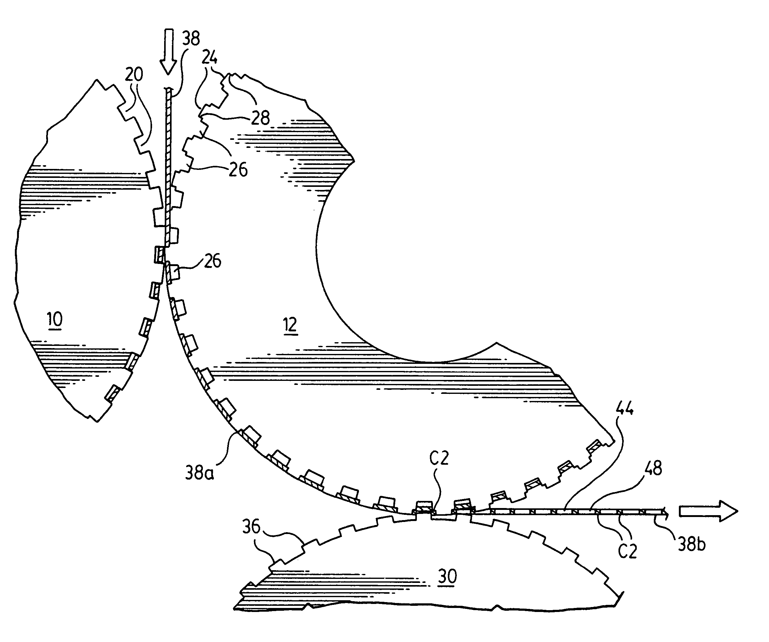
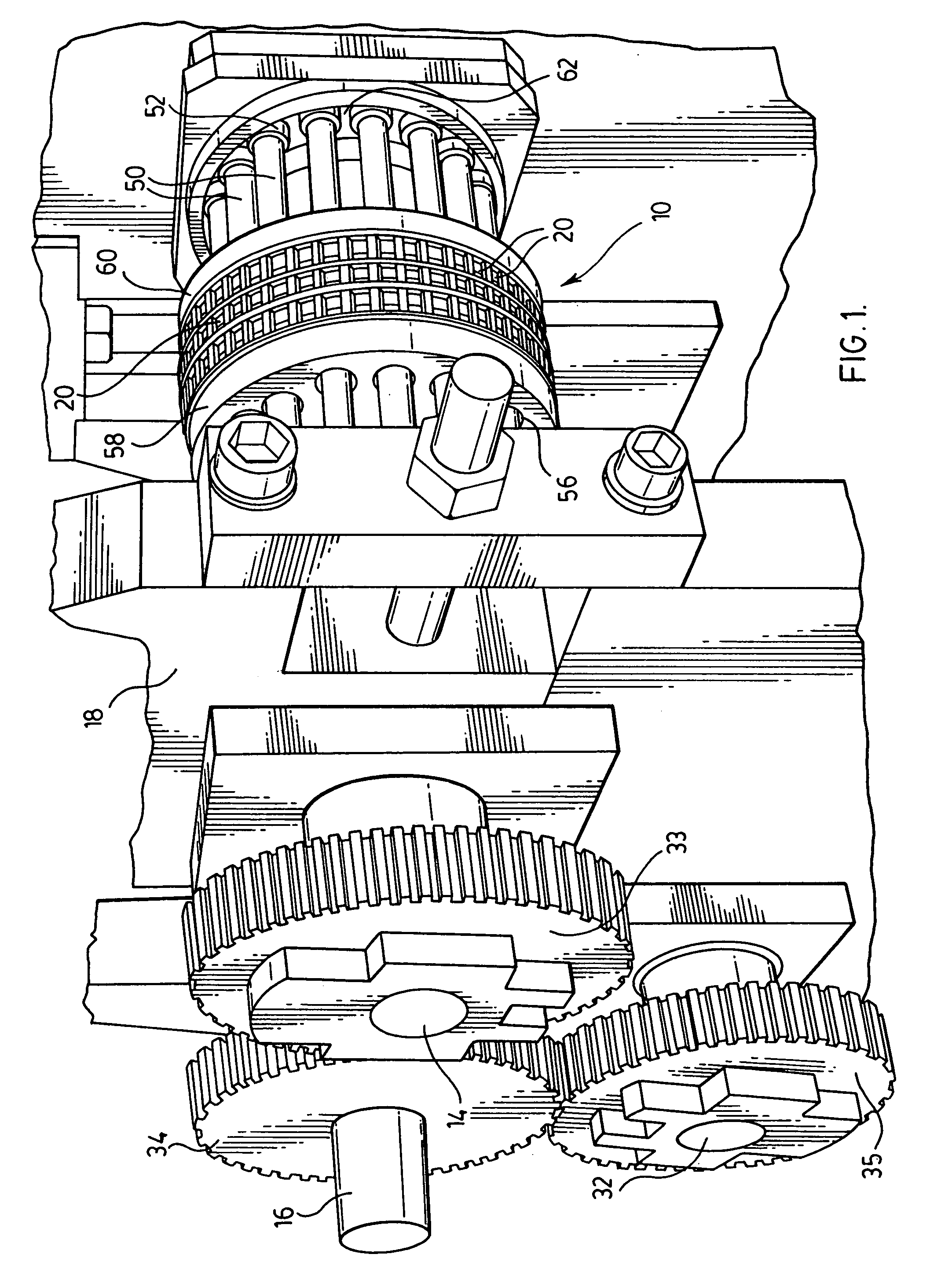
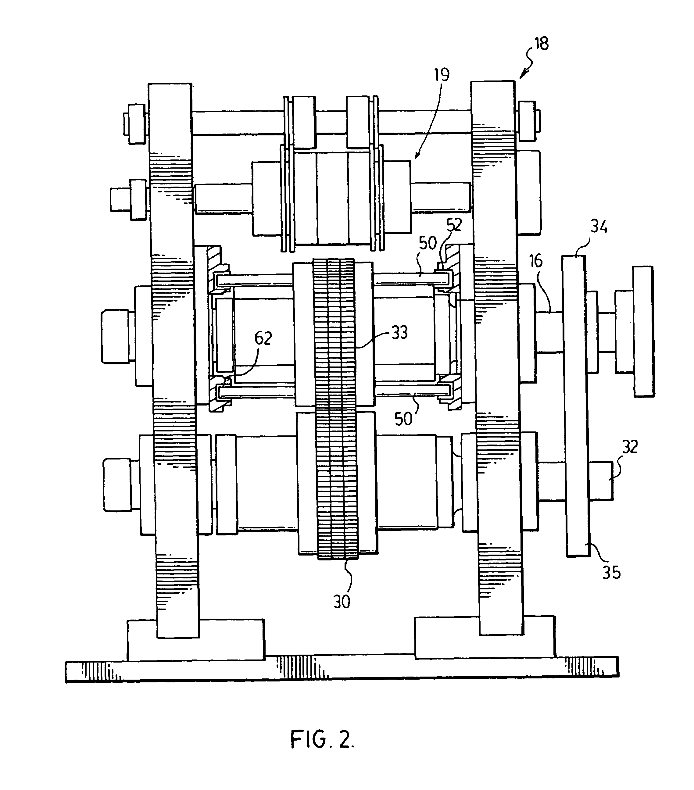
[0049]A prototype module illustrated most clearly in FIGS. 1, 2 and 9–11 was built to examine the viability of rotary hole punching. The machine utilized three rows of tooling to produce three transverse rows of punched holes in a given strip of lead alloy. For “Test 1”, cast and rolled forms of both pure and alloyed lead were run through the machine. Punching of the closely spaced and high tolerance holes was 100% successful.

[0050]The wire width of a lead alloy grid produced was about 0.030 inch and approximately 85% of the strip material was removed as waste. Up to about 96% the strip material can be removed as waste, leaving a wire thickness as thin as 0.010 inch. The thickness of strip material tested was about 0.030 inch.

Additional Tests

[0051]Seven more tests were conducted with the rotary punching machine, to determine whether it was capable of performing the same accurate and precise operation for producing 0.030 wire width on various materials, other than lead, with the foll...


PUM

PropertyMeasurementUnit
thicknessaaaaaaaaaa
thicknessaaaaaaaaaa
widthaaaaaaaaaa

Abstract

A method and apparatus for continuous, high-speed production of punched strip having an array of high-tolerance closely-spaced holes with positive ejection of waste punch-out material. A first pair of opposed rotary dies, one a female die and the other a male / female die, punches a first set of holes in a strip fed continuously between the dies, and a second pair of opposed rotary dies, one the male / female die and the other a male die, punches a second set of holes in the strip between the first set of holes, the strip being wrapped about the common male / female die during punching of the first and second sets of holes to continuously index the strip with the two opposed pairs of rotary dies to ensure production of the high-tolerance closely-spaced holes. A plurality of angular segments mounted in an annulus formed in proximity to the perimeter of the dies adapted for controlled radial travel of the angular segments during rotation of the dies, each angular segment having at least one ejector pin for radial reciprocal travel in a die recess, ejects punch-out material from the recess.

Description

BACKGROUND OF THE INVENTION[0001](i) Field of the Invention[0002]This invention relates to a method and apparatus for the punching of holes in deformable strip and, more particularly, relates to a method and apparatus for continuously punching an array of holes in deformable strips such as lead strip for the production of lead grids for use in the manufacture of lead-acid batteries.[0003](ii) Description of the Related Art[0004]Existing methods for punching material strips incur problems including low production speed, inadequate or no waste ejection, insufficient indexing precision, hole size and spacing tolerance errors, and the distortion or destruction of the final product. Previously, rotary punching of a deformable strip have employed rotary equipment having two or three shafts, each with a circumferentially distributed homogeneous male or female tool set. The rotation of adjacent shafts would be synchronized mechanically or electronically and their respective peripheral tools...

Claims


Application Information

Patent Timeline
Patent Type & Authority Patents(United States)
IPC IPC(8): B26D1/56B26F1/06B21D28/36B26D1/24B26F1/14B31B50/83
CPCB21D28/36Y10T83/0524Y10T83/04Y10T83/0515Y10T83/9389Y10T83/4836Y10T83/483Y02P70/50Y02E60/10B26D1/24B26F1/02B26F1/14
Inventor MARLOW, JOHN V.KILIC, OMER E.MAJOR, NIMROD I.
Owner TBS USA INC
Why Eureka
Try Eureka