Power drill/driver

a technology of power drill and driver, which is applied in the field of power tools, can solve the problems of further challenge for manufacturers, increased weight of power tools, so as to improve the clutch mechanism and limit the torsional output of power tools

Active Publication Date: 2006-06-27
BLACK & DECKER INC
View PDF68 Cites 108 Cited by
  • Summary
  • Abstract
  • Description
  • Claims
  • Application Information

AI Technical Summary

Benefits of technology

[0007]In another preferred form, the present invention provides a power tool having an improved clutch mechanism for limiting the torsional output of a transmission assembly. The clutch mechanism includes a clutch member that is fixedly coupled to a portion of the transmission assembly, such as the ring gear of a planetary-type reduction gear set. The clutch member includes a contoured clutch face against which a rotation-inhibiting element is biased. The torsional output of the transmission assembly is limited by the force that is exerted by the rotation-inhibiting element onto the clutch face. When the torque that is exerted on the portion of the transmission assembly exceeds a predetermined magnitude, the clutch member, along with the portion of the transmission assembly, rotates relative to the rotation inhibiting element to thereby limit the torsional output of the power tool.

Problems solved by technology

Manufacturers are further challenged by the demand of modern consumers for tools that are relatively smaller in size, lighter in weight and more powerful.
The use of threaded fasteners in these situations necessitates the incorporation of bosses to the transmission assembly and the clutch mechanism that tend to enlarge the size of the tool and which add a degree of weight to the power tool.
The fastening process itself tends to be relatively slow and errors in the process, such as over tightening, which can lead to the stripping of threads or cracking of the components, or under tightening, which can create an interference that prevents the components from operating properly, are possible.
The use of torque controlled fastening equipment is known to alleviate such processing errors, but this equipment can be relatively expensive to purchase and operate.
While configuration in this manner effectively accommodated consumer demands for both the base and torque controlled models in an economical manner, the modular configuration tended to add considerable length and weight to the power tool.

Method used


Image

  • Power drill/driver
  • Power drill/driver
  • Power drill/driver

Examples


Embodiment Construction

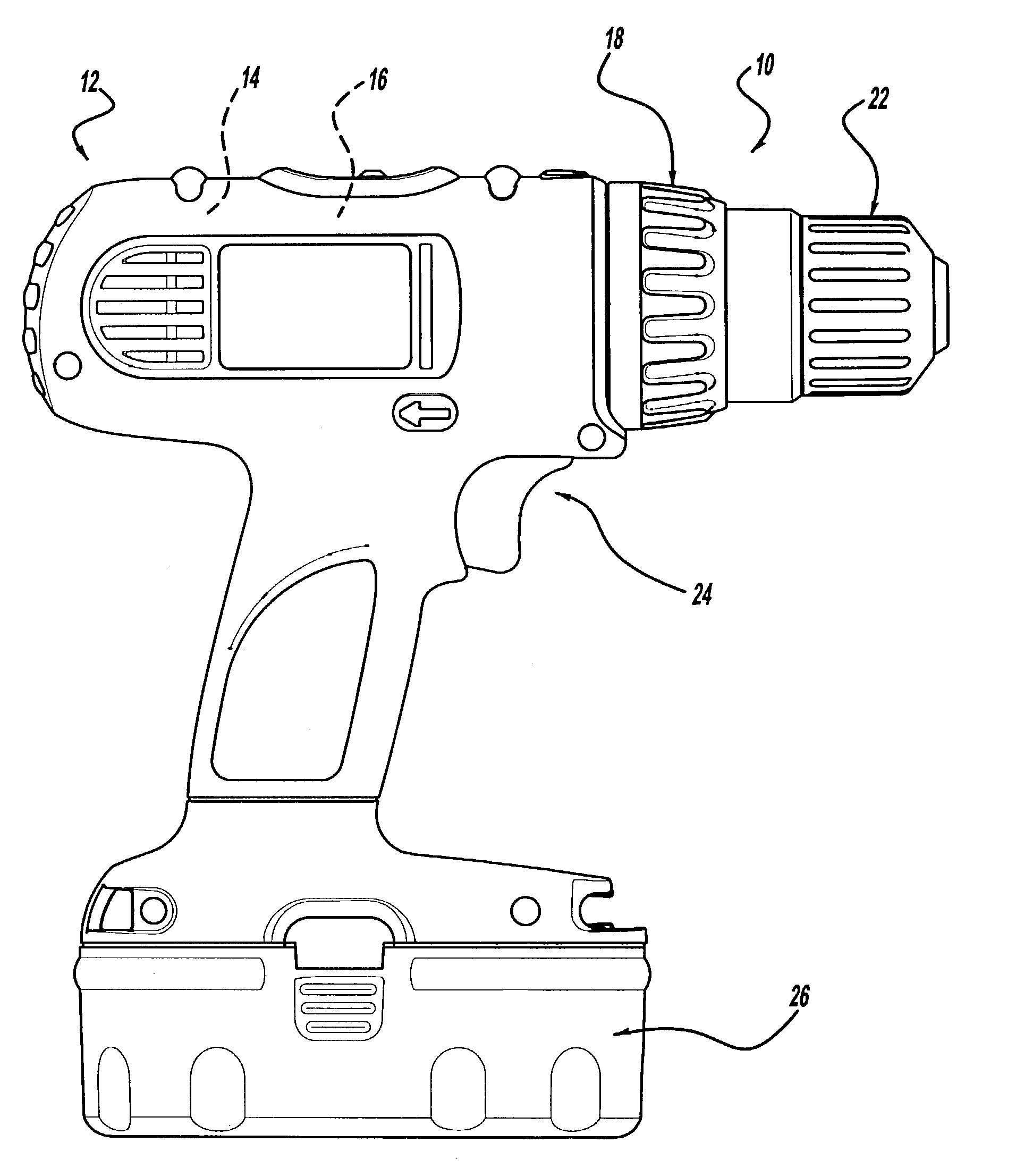
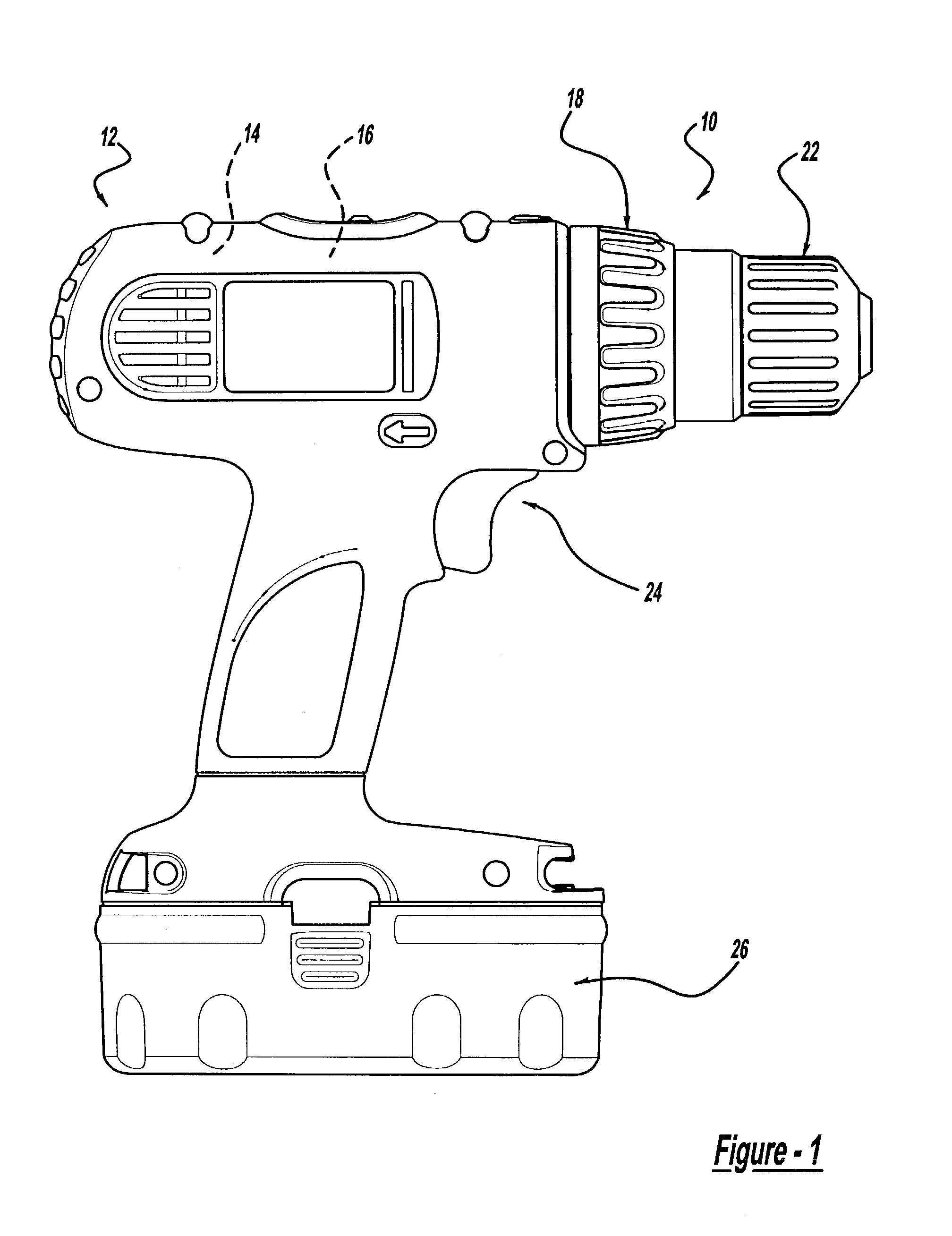
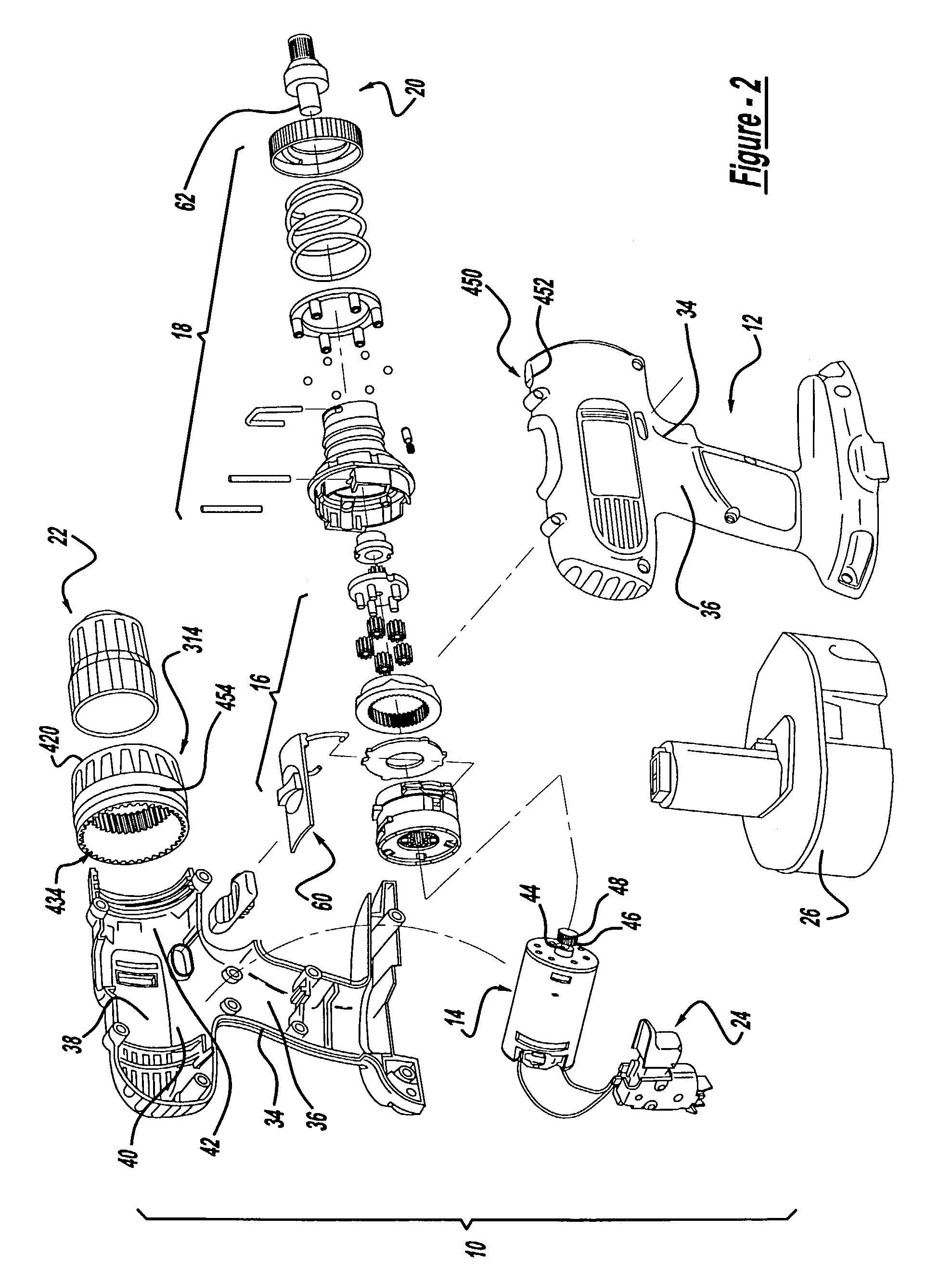
[0026]With reference to FIGS. 1 and 2 of the drawings, a power tool constructed in accordance with the teachings of the present invention is generally indicated by reference numeral 10. As those skilled in the art will appreciate, the preferred embodiment of the present invention may be either a cord or cordless (battery operated) device, such as a portable screwdriver or drill. In the particular embodiment illustrated, the power tool 10 is a cordless drill having a housing 12, a motor assembly 14, a multi-speed transmission assembly 16, a clutch mechanism 18, an output spindle assembly 20, a chuck 22, a trigger assembly 24 and a battery pack 26. Those skilled in the art will understand that several of the components of the power tool 10, such as the chuck 22, the trigger assembly 24 and the battery pack 26, are conventional in nature and therefore need not be discussed in significant detail in the present application. Reference may be made to a variety of publications for a more co...


PUM

PropertyMeasurementUnit
angleaaaaaaaaaa
speedaaaaaaaaaa
shapeaaaaaaaaaa

Abstract

A hand-held power tool having a multi-speed transmission and a clutch. The multi-speed transmission and the clutch are coupled to one another via a set of interconnecting tabs that are slidingly engaged to one another and secured with pins to inhibit the withdrawal of the tabs from one another. The clutch may include a clutch member, a unitarily formed clutch plate and a plurality of engagement members. The clutch plate includes an annular plate member and a plurality of leg members that extend generally perpendicularly from the annular plate member and which bias the engagement members into engagement with the clutch member. The clutch member may be coupled to an element of the multi-speed transmission, such as to the ring gear of a planetary gear set, so as to reduce the overall size of the power tool.

Description

CROSS-REFERENCE TO RELATED APPLICATIONS[0001]This application claims the benefit of U.S. Provisional Application No. 60 / 352,045, filed Jan. 25, 2002.FIELD OF THE INVENTION[0002]The present invention generally relates to power tools such as rotatable drills, power screwdrivers, and rotatable cutting devices. More specifically, the present invention relates to improvements in power tools and more particularly to the construction of a clutch mechanism and its coupling to a transmission.BACKGROUND OF THE INVENTION[0003]Modernly, manufacturers of power tools desire to reduce the cost of producing power tools by providing designs that provide the product with a high level of robustness while reducing complexity at the assembly level and minimizing components that do not add value to the product. Manufacturers are further challenged by the demand of modern consumers for tools that are relatively smaller in size, lighter in weight and more powerful.[0004]Accordingly, it is highly desirable ...

Claims


Application Information

Patent Timeline
Patent Type & Authority Patents(United States)
IPC IPC(8): B23B45/02B25B23/14F16D7/08
CPCB25B23/141F16D7/08Y10T408/65
Inventor DOYLE, MICHAEL C.PLATO, BARRY
Owner BLACK & DECKER INC
Why Eureka
Try Eureka