
Method of manufacturing thin film magnetic head

Inactive Publication Date: 2006-06-27
TDK CORPARATION
View PDF13 Cites 17 Cited by
  • Summary
  • Abstract
  • Description
  • Claims
  • Application Information

AI Technical Summary

Benefits of technology

[0025]The present invention has been conceived in view of the above-described problems. It is an object of the invention to provide a method of manufacturing a thin-film magnetic head that enables formation of the thin-film magnetic head with high precision and in a short time.
[0027]According to the method of manufacturing a thin-film magnetic head of the invention, the magnetic material layer is selectively etched and patterned by reactive ion etching, whereby at least one of the first and second magnetic layers is formed. Since the speed of etching process is generally faster with the reactive ion etching than the ion milling, at least one of the first and second magnetic layers can be formed in a short time.
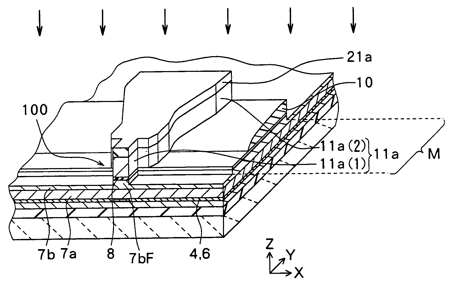
[0038]According to the method of manufacturing a thin-film head of the invention, the first etching process is performed with reactive ion etching, and then the second etching process is performed with focused ion beam etching, so that a magnetic pole tip composed of the first uniform width portion, a portion of the gap layer corresponding to the first uniform width portion and the second uniform width portion is formed. Since etching process with the focused ion beam etching enables processing with higher precision than the etching process with reactive ion etching, the width of the magnetic pole can be reduced with high precision by forming the magnetic pole through both the first and second etching processes as compared with the case where only the first etching process is performed.

Problems solved by technology

However, the applicants have confirmed that the ion milling brings about the following problems.
This deteriorates precision in forming the mask due to adverse effects of the light reflected from the surface of the underlying permalloy layer having a high reflectance.
Further, according to the method of the related art, the pole tip 200 is formed by ion milling with a lower etching rate, and therefore etching process takes a long time, requiring a considerable time to finish processing of the pole tip 200.

Method used


Image

  • Method of manufacturing thin film magnetic head
  • Method of manufacturing thin film magnetic head
  • Method of manufacturing thin film magnetic head

Examples


first embodiment

[0075]An exemplary method of manufacturing a composite thin-film magnetic head as a method of manufacturing a thin-film magnetic head according to a first embodiment of the invention will be described with reference to FIGS. 1A and 1B to FIG. 11. The thin-film magnetic head of this embodiment will be described together with the method of manufacturing a thin-film magnetic head of this embodiment because it is embodied by this method.

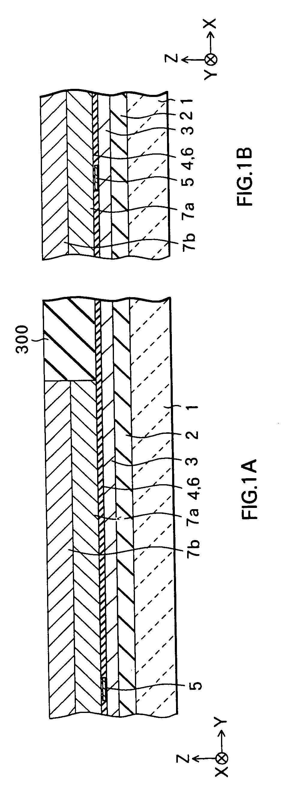
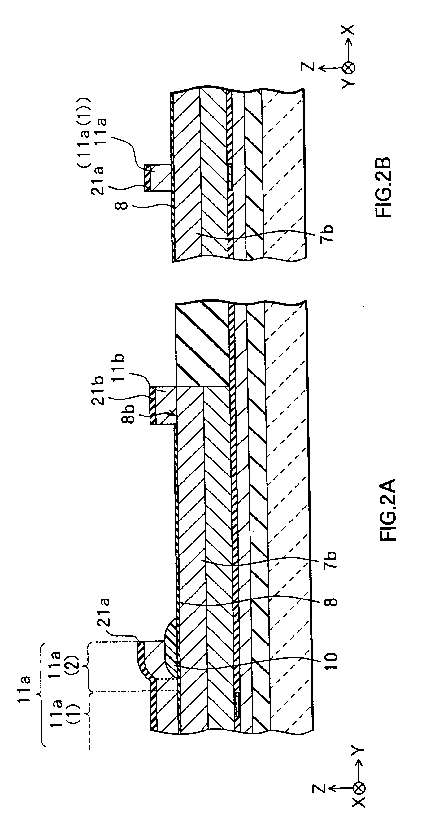
[0076]Each FIGS. 1A to 5A illustrates a cross section perpendicular to an air bearing surface, while each FIGS. 1B to 5B illustrates a cross section in parallel to the air bearing surface of a pole. FIG. 6 to FIG. 11 are perspective views corresponding to major manufacturing process. More specifically, FIG. 9 to FIG. 11 correspond to the states shown in FIG. 2, FIG. 3, and FIG. 5, respectively. It should be noted, however, that an insulating film 12, a thin-film coil 13, and the like in FIG. 3 are not shown in FIG. 10, and that insulating films 12 and 14...

second embodiment

[0137]A second embodiment of the present invention will next be described.

[0138]A method of manufacturing a composite thin-film magnetic head as a method of manufacturing a thin-film magnetic head according to a second embodiment of the invention will be described with reference to FIGS. 21A and 21B to FIGS. 25A and 25B. A thin-film magnetic head according to this embodiment will also be described because it is embodied by the method of manufacturing a thin-film magnetic head of this embodiment. Each of FIG. 21A to FIG. 25A illustrates a cross section perpendicular to the air bearing surface, while each of FIG. 21B to FIG. 25B illustrates a cross section in parallel to the air bearing surface of the pole. The notations related to X, Y, and Z axis directions in FIGS. 21A and 21B to FIGS. 25A and 25B are the same as those in the above-described first embodiment, and the components in these figures identical to those in the first embodiment are indicated by the same reference character...


PUM

PropertyMeasurementUnit
Temperatureaaaaaaaaaa
Widthaaaaaaaaaa

Abstract

A method of manufacturing a thin-film magnetic head allowing dimension control of the width of the magnetic pole and reduction of the time required for formation is provided. A layer of iron nitride formed by sputtering is selectively etched with the RIE to form a top pole tip. In this etching process with RIE, chlorine-type gas is selected as a gas seed for etching, and the process temperature is in a range of 50° C. to 300° C. Subsequently, using part of a first mask and a tip portion of the top pole tip as a mask, part of both the write gap layer and the second bottom pole are etched with the RIE similarly to the above process, to thereby form a magnetic pole. The etching conditions are optimized by performing the process with the RIE under the above conditions, so that both of the top pole tip and the magnetic pole can be formed with high precision, and that the time required for forming both of these elements can be significantly reduced.

Description

[0001]This is a Continuation of U.S. patent application Ser. No. 09 / 765,293 filed on Jan. 22, 2001, now issued as U.S. Pat. No. 6,669,855, the contents of which are incorporated herein in its entirety.BACKGROUND OF THE INVENTION[0002]1. Field of the Invention[0003]The present invention relates to a method of manufacturing a thin-film magnetic head having at least an inductive-type magnetic transducer for writing.[0004]2. Description of the Related Art[0005]Improvements in the performance of a thin-film magnetic head have been sought since a surface recording density of a hard disk drive has been improved. A composite thin-film magnetic head having a structure in which, a recording head having an inductive-type magnetic transducer for writing and a reproducing head having a magnetoresistive (hereinafter referred to as MR) element for reading are stacked, is widely used as the thin-film magnetic head. The MR element includes an AMR element using an anisotropic magnetoresistive (herein...

Claims


Application Information

Patent Timeline
IPC IPC(8): B44C1/22G11B5/127G11B5/31
CPCG11B5/3116G11B5/3163Y10T29/49043Y10T29/49052Y10T29/49046
Inventor SASAKI, YOSHITAKAIIJIMA, ATSUSHIYARI, SEIJIKANAKUBO, KATSUYA
Owner TDK CORPARATION
Learn More