Joint structure of superconducting cable and insulating spacer for connecting superconducting cable

a superconducting cable and insulating spacer technology, applied in the direction of connection contact member materials, superconductor devices, coupling device connections, etc., can solve the problems of reducing the service life of the superconducting cable. , to achieve the effect of reducing the length of the joint structure in the longitudinal direction of the cable and facilitating the connection

Inactive Publication Date: 2006-06-27
SUMITOMO ELECTRIC IND LTD
View PDF6 Cites 18 Cited by
  • Summary
  • Abstract
  • Description
  • Claims
  • Application Information

AI Technical Summary

Benefits of technology

[0031]Such provision of the connecting portion of the conductor connecting member and the long conductor within the hollow tube is advantageous in that the length of the joint structure in a longitudinal direction of the cable is shortened. A material of the hollow tube is not restrict...

Problems solved by technology

When the above-described method of connecting the central conductor of the insulating spacer with a normal conducting cable end is employed for connection with a superconducting cable end, however, a superconducting layer (superconducting wire) within the superconducting cable is prone to damage, in which case superconductivity cannot be guaranteed.
Further, it is difficult to directly connect the central conductor of the insulating spacer, generally made of a metal having aluminum or copper as its main body, with the superconducting cable completely different in material and structure therefrom.
This connecting method, however, still poses the following problems:It is often difficult to connect the central conductor of the insulating spacer to the conductor connecting member by using welding, particularly welding employing an electron beam...

Method used


Image

  • Joint structure of superconducting cable and insulating spacer for connecting superconducting cable
  • Joint structure of superconducting cable and insulating spacer for connecting superconducting cable
  • Joint structure of superconducting cable and insulating spacer for connecting superconducting cable

Examples


second embodiment

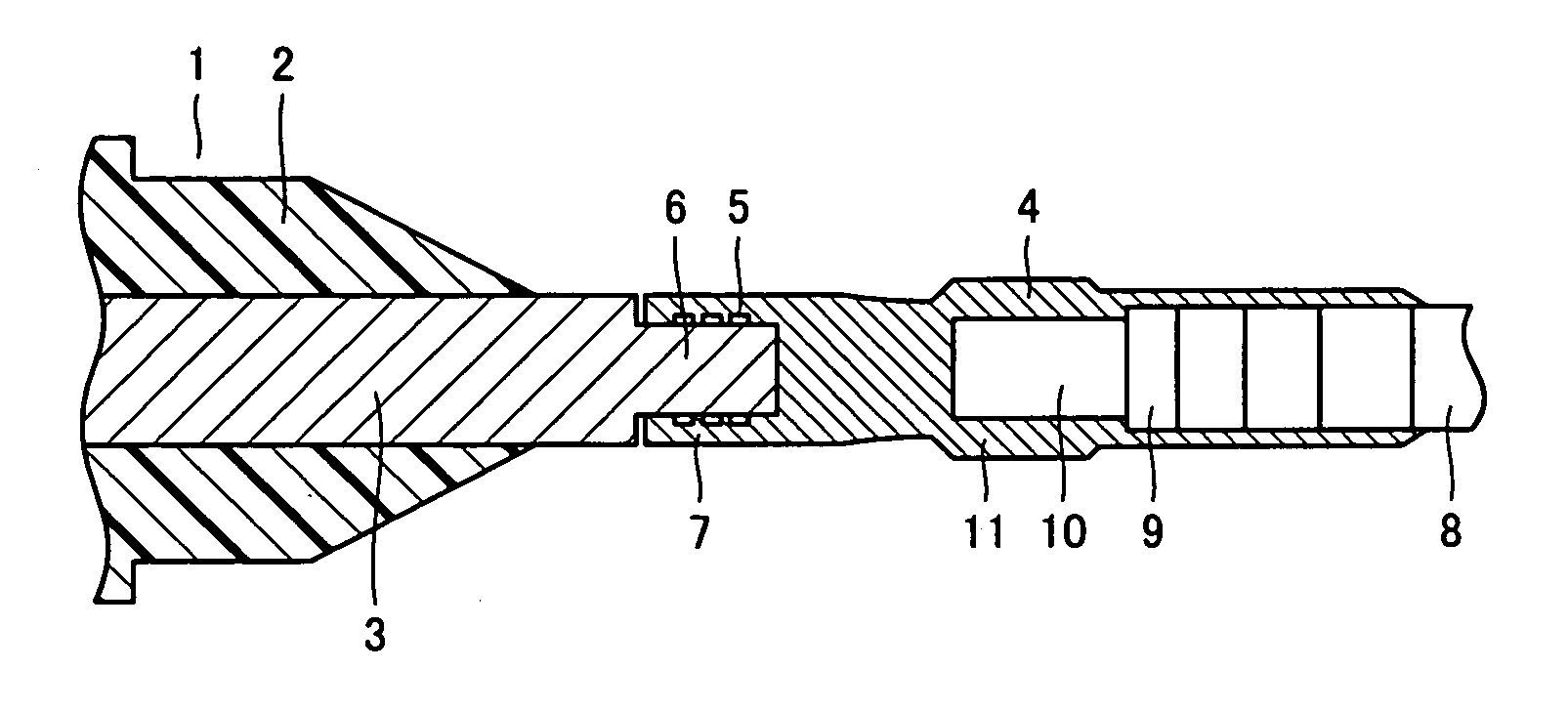
[0043]In the case where a metal having aluminum as its main body is used for central conductor 3 and a metal having copper as its main body is used for conductor connecting member 4, it is difficult to achieve connection of sufficient strength with soldering or brazing between the metals of different kinds. To solve this problem, the present invention employs multi-contact connection as described above.

[0044]Specifically, in the example shown in FIG. 1, multi-contact connection is used for connection between central conductor 3 and conductor connecting member 4. More specifically, conductor connecting member 4 has a concave portion 7 at its end. Concave portion 7 has an inner periphery provided with three grooves 5, with a conductive elastic body (not shown) inserted therein. Provided at an end of central conductor 3 is a projecting portion 6 having a diameter slightly smaller than the inner diameter of concave portion 7. Projecting portion 6 is inserted into concave portion 7.

[0045...

third embodiment

[0047]In the present invention, central conductor 3 and conductor connecting member 4 are connected to each other by friction welding, rather than multi-contact connection. In the friction welding, portions of the members to be connected (in the example of FIG. 1, central conductor 3 and conductor connecting member 4) are brought into contact with each other, and one of the two members is rotated (or the both members are rotated at different speeds in different directions from each other) to generate heat by contact friction. With the rotation stopped, the members are bonded by means of the frictional heat generated and a pressure applied to the connecting portion. With this friction welding, again, the connection between central conductor 3 and conductor connecting member 4 can readily be achieved even at a site where the terminating portion is to be placed, and the connecting portion allows a large amount of current to flow therethrough.

fourth embodiment

[0048]Hereinafter, the present invention is described.

[0049]Conductor connecting member 4 shown in FIG. 1 has its other terminal connected to a terminal of superconducting cable 8. Superconducting cable 8 in the example of FIG. 1 has a structure similar to that of the conventional superconducting cable shown in FIG. 6.

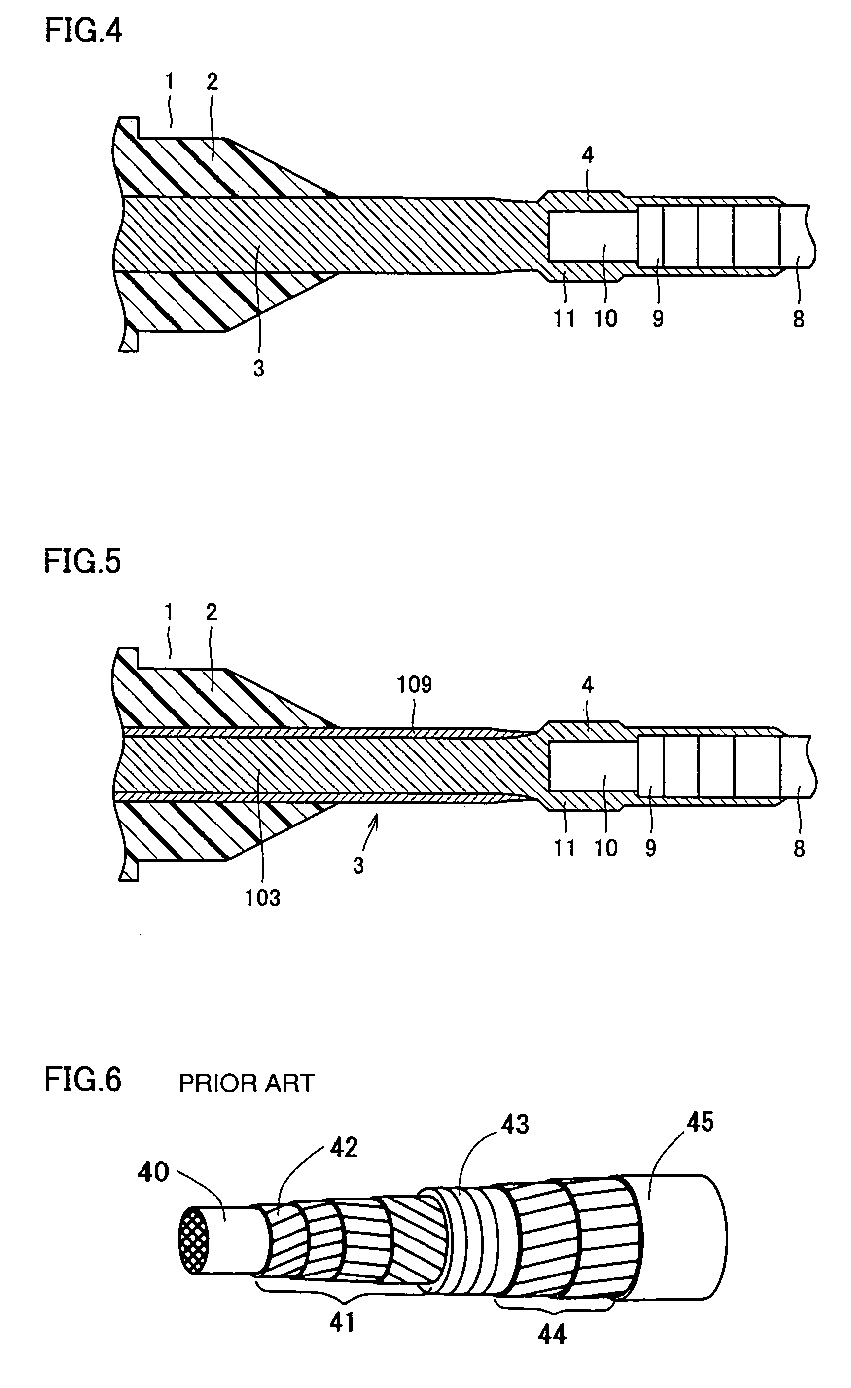
[0050]Specifically, superconducting cable 8 of the fourth embodiment has a former 10 made of a metal wire at the core, which is covered with a superconducting layer 9, an insulating layer, a shield layer and a protective layer in this order. At the portion to be connected with conductor connecting member 4, the insulating layer, the shield layer and the protective layer are removed, and the respective layers of superconducting layer 9 and former 10 are exposed stepwise.

[0051]Superconducting layer 9 is connected to conductor connecting member 4 by soldering. In the example shown in FIG. 1, superconducting layer 9 is formed in four layers, which are each connected to con...


PUM


Abstract

A joint structure of a superconducting cable having improved connection strength and preventing break of a superconducting layer is provided. A central conductor of an insulating spacer and a superconducting cable are connected via a conductor connecting member having a sleeve-shaped end. Specifically, the central conductor of the insulating spacer and the conductor connecting member are connected by multi-contact connection.

Description

BACKGROUND OF THE INVENTION[0001]1. Field of the Invention[0002]The present invention relates to a joint structure and an insulating spacer applied for connection of a superconducting cable. More particularly, the present invention relates to a structure connecting a superconducting cable terminal to a central conductor of an insulating spacer for use in insulating the superconducting cable terminal from a grounded portion, at a terminating portion of the superconducting cable or at a connecting portion of two superconducting cables, and the insulating spacer for use in such connection.[0003]2. Description of the Background Art[0004]FIG. 6 is a perspective view of a representative example of a superconducting cable. The superconducting cable has a former 40 made of a metal wire at the core, and a superconducting layer (a superconducting wire) 41 covering former 40. Superconducting layer 41 generally consists of a tape-shaped superconducting wire 42 having superconducting filaments p...

Claims


Application Information

Patent Timeline
IPC IPC(8): H01R4/00H01B12/02H01B12/00H01R4/68H01R43/00H02G1/14H02G15/08
CPCH01R4/68H02G15/34Y02E40/648Y02E40/60H01B12/02H01B12/12
Inventor ASHIBE, YUUICHIMASUDA, TAKATOTAKAHASHI, YOSHIHISAMATSUO, KIMIYOSHIHONJO, SHOICHIMIMURA, TOMOO
Owner SUMITOMO ELECTRIC IND LTD
Why Eureka
Try Eureka