Unlock instant, AI-driven research and patent intelligence for your innovation.

Light source control system

a control system and light source technology, applied in the direction of electric variable regulation, lasers, instruments, etc., can solve the problem of reducing the time required to obtain a stable power level, and achieve the effect of stable power level, constant optical power output, and reduced time requirements

Active Publication Date: 2006-06-27
OZ OPTICS
View PDF11 Cites 8 Cited by
  • Summary
  • Abstract
  • Description
  • Claims
  • Application Information

AI Technical Summary

Benefits of technology

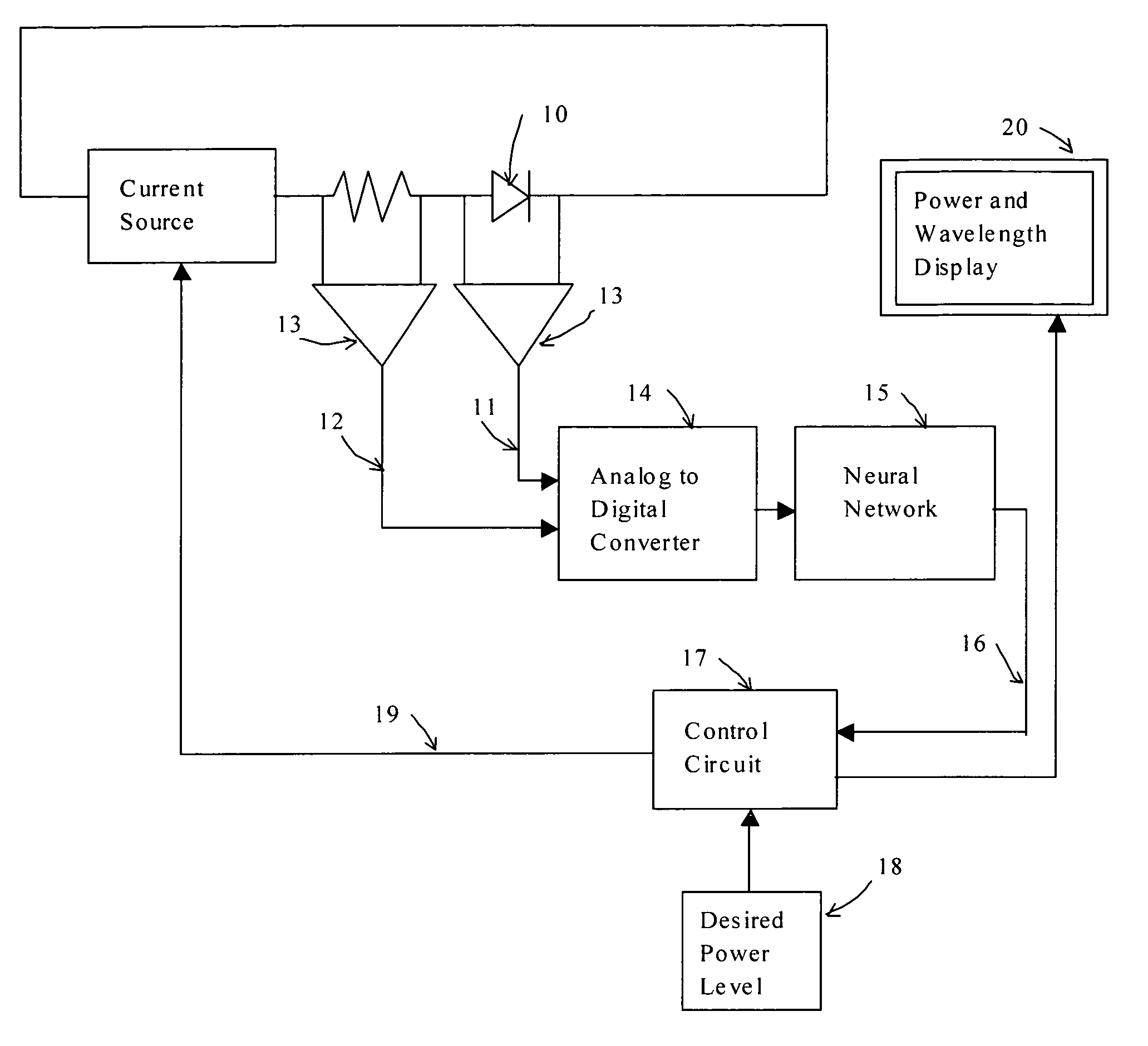
"The present invention provides a software-based system that uses a neural network to actively adjust the power of a light source to maintain a constant optical power output. This system is adaptable to different load-voltage relationships and can be used in both open and closed loop systems. Additionally, compensation for non-linearity is optionally provided by the control system. The system is indirectly based on the temperature of the light source and does not require a physical temperature sensor for temperature measurement. Furthermore, the system dynamically adjusts the power levels to the desired value, even while the light source is warming up, which significantly reduces the time required to obtain a stable power level."

Problems solved by technology

Furthermore, since a conventional light source often requires significant time to stabilize when first turned on, the system dynamically adjusts the power levels to the desired value, even while the light source is warming up, which significantly reduces the time required to obtain a stable power level.

Method used


Image

  • Light source control system
  • Light source control system
  • Light source control system

Examples


Embodiment Construction

[0021]The system of the present invention uses a neural network to develop a model of a light source. In order to use a neural network, a set of data must first be generated through what is known as a training period. The data set is obtained through several measurements of the optical output power and the wavelength of the light source under different conditions of applied voltage, current and temperature of the source. The data set is then used to train a neural network or adaptive system and develop a model.

[0022]To produce the data, various drive currents are applied through a light source, while the resulting voltage across the source and the optical power and wavelengths produced by the source are measured. Several measurements are performed as the temperature of the source is changed. Typically, measurements take place within an environmental chamber, although embodiments that incorporate a self-contained heating or cooling system such as a Peltier element may also be used to...


PUM


Abstract

A system and method for controlling an optical light source is provided. A current source drives the light source, while the voltage across and the current through the light source is measured. The voltage and current are converted to digital signals and sent to a neural network, which generates a modeled optical output power of the light source and a modeled value of the optical wavelength. A control circuit receives the modeled optical output power and wavelength and sends a control signal to the current source to minimize the difference between the desired power output and the modeled output power. In addition, a control signal is sent to a Peltier driver to control the temperature of a Peltier cooler in order to increase or decrease the wavelength emitted by a laser diode.

Description

CROSS REFERENCE TO RELATED APPLICATIONS[0001]This application claims the benefit under 35 U.S.C. 119(e) of U.S. Provisional Application No. 60 / 545,531 filed Feb. 19, 2004.BACKGROUND OF THE INVENTION[0002]1. Field of the Invention[0003]This invention relates to the control system for an optical light source through use of a neural network. Although primarily intended for the fiber optics industry, applications extend to any industry that requires a stable optical source.[0004]2. Background Information[0005]There are numerous types of light sources currently in existence. However, the intensity and wavelength of the light that is produced may vary, depending on parameters such as voltage across the light source, current flowing through the light source, and temperature of the light source. Methods exist to minimize effects caused by variations in these parameters, in either an open loop or closed loop configuration. In the closed loop configuration, a feedback or error signal is provi...

Claims


Application Information

Patent Timeline
Patent Type & Authority Patents(United States)
IPC IPC(8): H05B37/02G05F1/00H01S3/13
CPCH05B33/0854H05B33/0851H05B45/12H05B45/14H05B45/18
Inventor YOULE, GORDON DAVID
Owner OZ OPTICS