
Integrated multipath limiting ground based antenna

a ground-based antenna and multi-path technology, applied in the direction of polarised antenna unit combinations, resonant antenna combinations, independent non-interacting antenna combinations, etc., can solve the problems of time delay, time delay is a significant problem, multi-path is troublesome for navigation ranging systems, etc., to achieve excellent gain and phase stability, excellent multi-path performance, and minimal group delay

Inactive Publication Date: 2006-06-27
DB SYST
View PDF21 Cites 21 Cited by
  • Summary
  • Abstract
  • Description
  • Claims
  • Application Information

AI Technical Summary

Benefits of technology

[0015]The above stated system requirements led to the development of a dual beam antenna system which significantly reduces multipath errors before they enter the receiver front end.
[0016]Another objective of the invention was to create an antenna which provides full hemispherical coverage while maintaining excellent multipath performance as well as excellent gain and phase stability with minimal group delay over the operational frequency band. The invention consists of the integration of a High Zenith Antenna (HZA) and a Multipath Limiting Antenna (MLA) which together form the Integrated Multipath Limiting Antenna (IMLA). The HZA receives GPS information from high elevation satellites (30 degrees through 90 degrees) at all azimuths and the MLA receives GPS information from low elevation satellites (2 degrees through 35 degrees) at all azimuths.

Problems solved by technology

Multipath is troublesome to navigation ranging systems when the signal amplitude of the multipath is strong relative to the direct signal.
In addition, since reflections and diffractions involve larger path lengths than the direct signal, they incur a time delay, which can affect GPS code or carrier measurements.
This time delay is a significant problem for GPS since it performs time-based ranging measurements.
Ground multipath from satellite transmissions is the largest error source for the LAAS because of its close proximity to the ground and its nearly static geometry.

Method used


Image

  • Integrated multipath limiting ground based antenna
  • Integrated multipath limiting ground based antenna
  • Integrated multipath limiting ground based antenna

Examples


Embodiment Construction

[0115]I. Multipath Limiting Antenna (MLA)

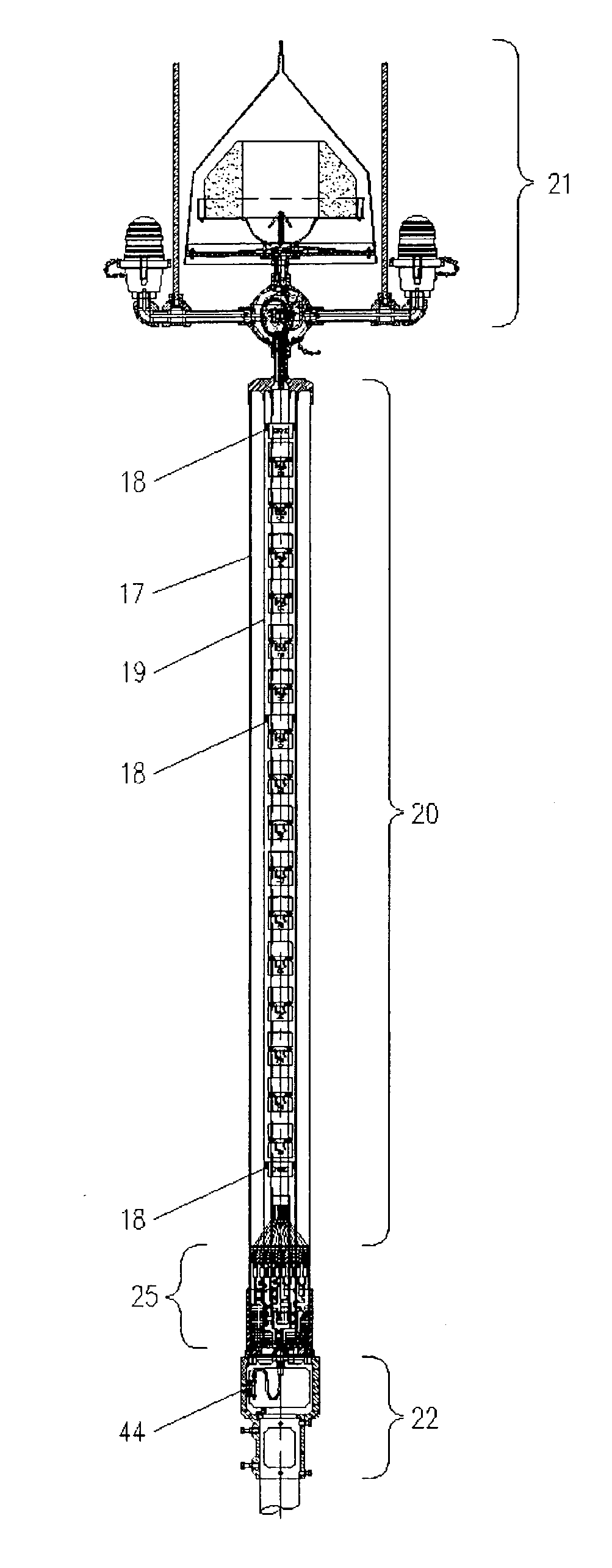
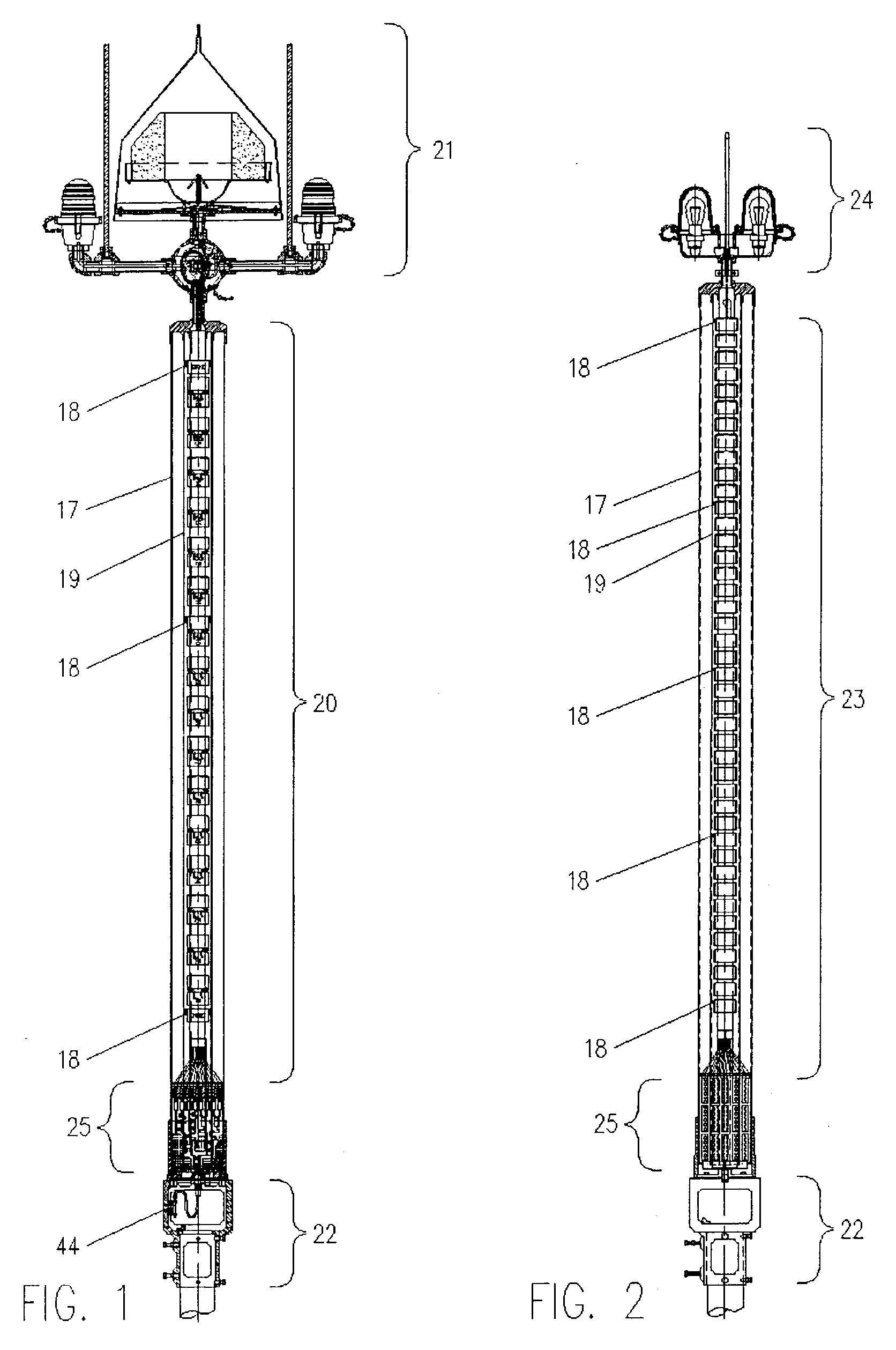
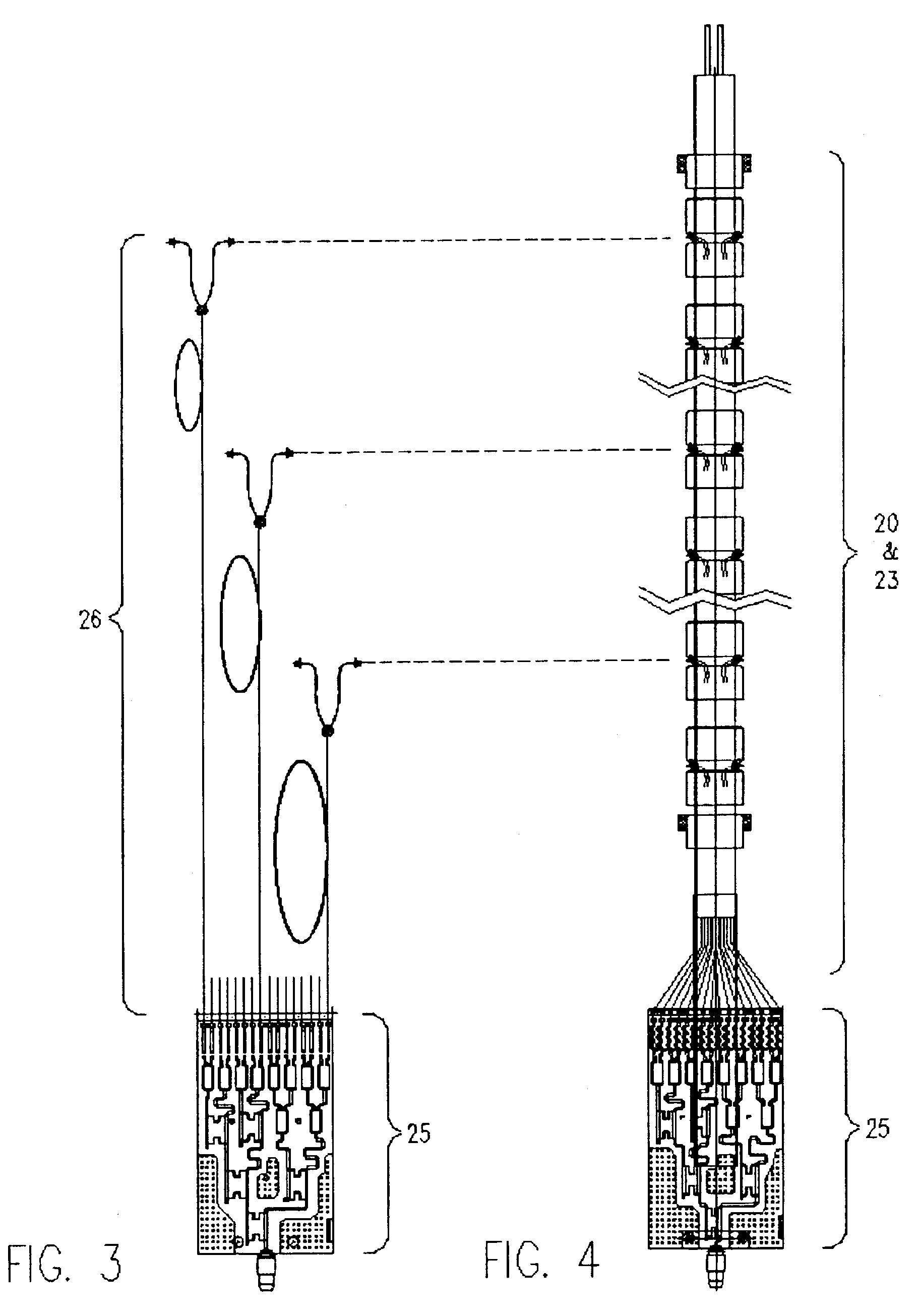
[0116]FIG. 1 illustrates an integrated multipath-limiting antenna (IMLA) which includes: MLA array multi element 20, high zenith antenna (HZA) 21 and a pipe adaptor for antenna mounting 22. The MLA has a coaxially configured outer radome fiberglass 17 and inner radome fiberglass 19 for greater strength, durability, longitudinal stiffness and a means to heat (de-ice) the antenna when required. The High Zenith Antenna (HZA) includes air terminals, dual obstruction lights and a junction box.

[0117]For detailed theory of operation of the MLA refer to FIG. 5, where central metal support tube 2 contains a RF power / phase coax transmission line system 1 which comes from a signal source (receiver or transmitter or both). The RF power / phase coax transmission line system 1 goes thru the wall of the central metal support tube 2, via coax feed thru 4, 1&2 are fastened together securely locked and soldered so that no RF energy is fed into the inside of cent...


PUM


Abstract

An integrated dual antenna system for Global Positioning System (GPS), Local Area Augmentation System (LAAS), ground based subsystem surface mounted (pole / tower / platform / other) and coaxially stacked (over and under). The dual antenna and receiver system is specifically designed and tuned to receive only the direct GPS satellite ranging signals while highly rejecting the ground multipath (indirect) signals. The upper antenna is a Right Hand Circularly Polarized (RHCP) omni-directional High Zenith Antenna (HZA) with dual obstruction lights and dual air terminals. The lower antenna is an electrically long vertically polarized omni-directional linear phased array having a very sharp horizon cut off and is a Multipath Limiting Antenna (MLA). When the two antennas (MLA and HZA) are mounted together they become the Integrated Multipath Limiting Antenna (IMLA). Interoperability is assured by high RF isolation between antennas. Both antennas are broad-band and have precisely controlled vertical and horizontal radiation patterns. Together the radiation patterns cover the complete upper hemisphere where satellites are visible.

Description

[0001]This application claims the benefit of U.S. Provisional Application No. 60 / 378,700 filed May 6, 2002.BACKGROUND OF THE INVENTION[0002]The Local Area Augmentation System (LAAS) is in the late stages of being developed to support the differential Global Navigational Satellite System (GNSS) based aircraft precision approaches and landings. Applications other than precision approach and landing may also be supported. The LAAS, when implemented using the Global Positioning System (GPS) as the source of satellite navigation signals, is known as the GPS / LAAS and is shown in FIG. 17. It consists of three primary subsystems:[0003]A) The satellite subsystem, which produces ranging signals. This standard explicitly addresses the use of GPS and SBAS (satellite based augmentation system). Provision has been made for the use of other satellite systems such as the Russian GLONASS.[0004]B) The ground subsystem, which provides a VHF data broadcast (VDB) containing differential corrections and ...

Claims


Application Information

Patent Timeline
IPC IPC(8): H01Q21/28H01Q1/06H01Q1/12H01Q21/26
CPCH01Q1/06H01Q21/28H01Q21/26H01Q1/1242H01Q9/0464H01Q19/00
Inventor THORNBERG, D. BRYCETHORNBERG, DEAN S.
Owner DB SYST
Learn More