Efficient waveguide arrays with optimized matching transitions

a waveguide array and matching transition technology, applied in the field of waveguide arrays, can solve problems such as substantial loss, and achieve the effects of improving efficiency, low loss imaging, and optimizing matching transitions

Inactive Publication Date: 2006-06-27
CISPARIE GROUP LIABILITY
View PDF4 Cites 15 Cited by
  • Summary
  • Abstract
  • Description
  • Claims
  • Application Information

AI Technical Summary

Benefits of technology

[0003]The present invention, efficient waveguide arrays with optimized matching transitions, provides low loss imaging by using waveguide arrays. A planar array of radial waveguides has improved efficiency realized by combining the array with a segmented arrangement of matching sections. The array is connected to a slab waveguide, containing the array focal point, and the purpose of the matching sections is to substantially improve the efficiency of power transfer to the vicinity of the focal point. Without matching sections, substantial loss would be caused by power transfer from the fundamental mode to two particular unwanted modes of the slab, namely the two modes with the closest propagation constants to the fundamental mode. Accordingly, my invention essentially eliminates this loss by including between the array and the slab

Problems solved by technology

Without matching sections, substantial loss would be caused by power transfer from the fundamental mode to two partic

Method used


Image

  • Efficient waveguide arrays with optimized matching transitions
  • Efficient waveguide arrays with optimized matching transitions
  • Efficient waveguide arrays with optimized matching transitions

Examples


Embodiment Construction

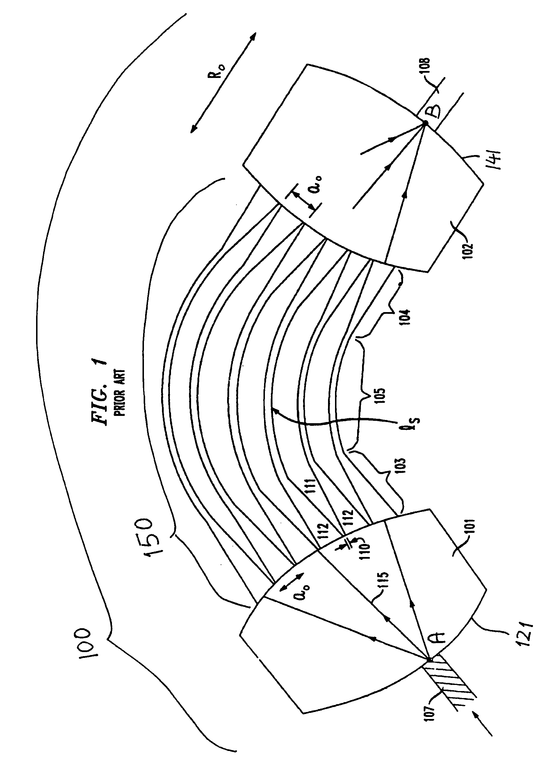
[0023]In the following description, identical element designations in different figures represent identical elements. Additionally in the element designations, the first digit refers to the figure in which that element is first located (e.g., 102 is first located in FIG. 1).

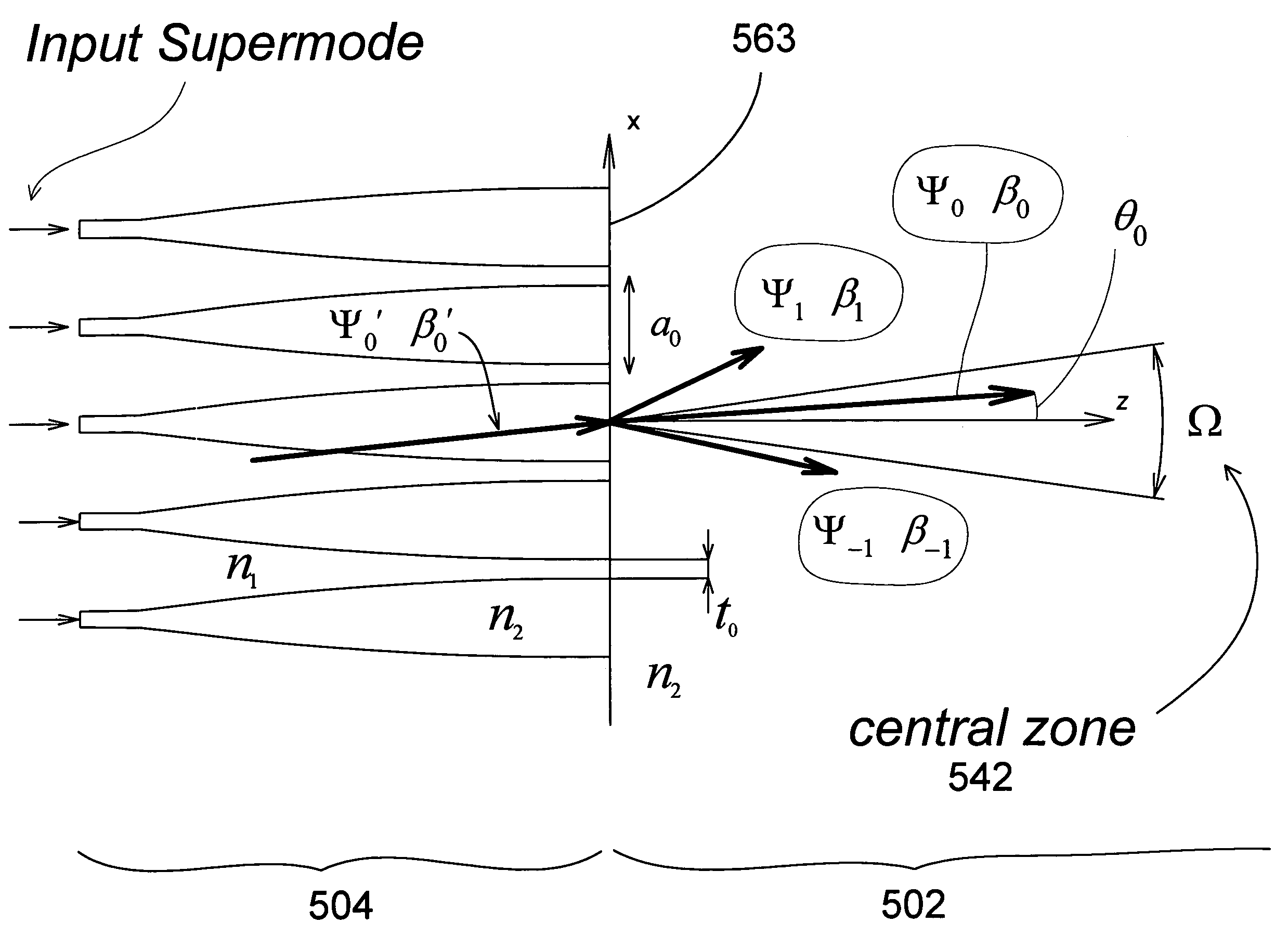
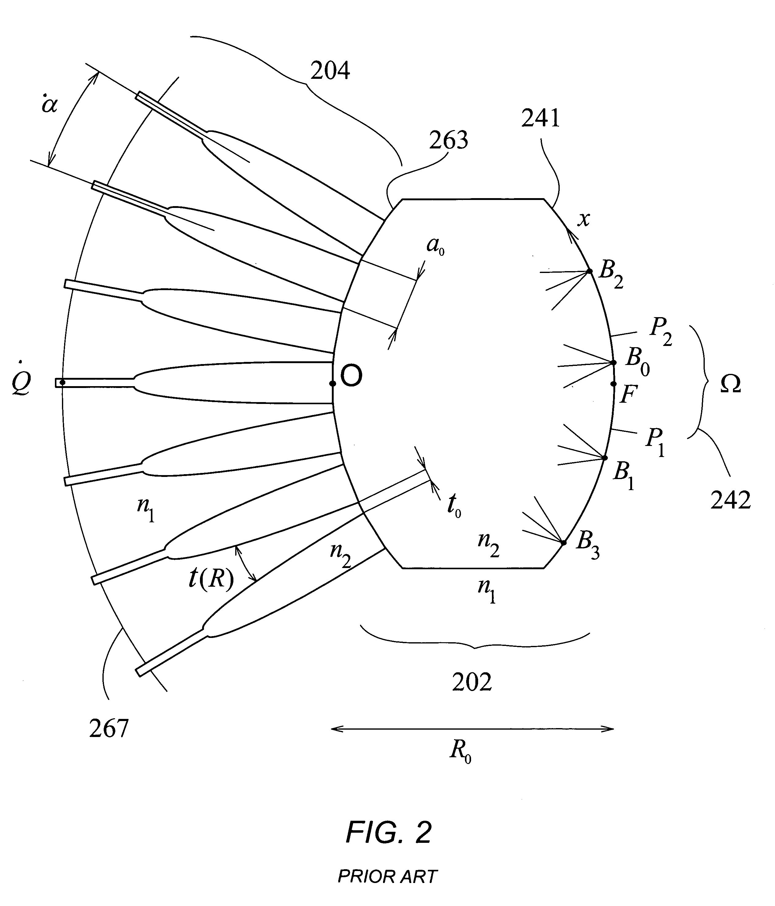
[0024]The present invention, efficient waveguide arrays with optimized matching transitions, provides low loss imaging by using waveguide arrays. A planar array of radial waveguides has improved efficiency realized by combining the array with a segmented arrangement of matching sections. The array is connected to a slab waveguide, containing the array focal point, and the purpose of the matching sections is to substantially improve the efficiency of power transfer to the vicinity of the focal point. Without matching sections, substantial loss would be caused by power transfer from the fundamental mode to two particular unwanted modes of the slab, namely the two modes with the closest propagation constants to the ...


PUM


Abstract

An optical interconnection apparatus including waveguide arrays such as waveguide lenses, waveguide gratings and star couplers, has improved efficiency realized using a periodic array combined with an arrangement of matching sections. The array is connected to a slab region containing the array focal point and the purpose of the matching sections is to minimize unwanted radiation by the array outside the central zone of the array. This unwanted radiation is primarily caused by two particular unwanted modes excited at the array junction with the slab, and the resulting loss is minimized by properly choosing the average phase shift applied by each section to said unwanted modes.

Description

FIELD OF THE INVENTION[0001]This invention relates to waveguide arrays in optical systems, and more particularly, to waveguide arrays having improved efficiency for wavelength routers and star couplers in integrated optics.BACKGROUND OF THE INVENTION[0002]Waveguide arrays are used optical wavelengths to realize imaging lenses and gratings in wavelength routers. One such wavelength grating router is described in U.S. Pat. No. 5,136,671, issued on Aug. 4, 1992. As shown in FIG. 1, this router is an imaging arrangement formed by a waveguide grating and it is generally composed of two dielectric slabs, 101 and 102, two periodic arrays 103 and 104, and a set of waveguides (grating arms), 105, of different lengths between the two arrays. Typically, in commercial routers the loss exceeds 3 db for the central ports of the router and, for the marginal ports it often exceeds 6 db. Such losses seriously limit the usefulness of the router for passive networks and applications such as channel dr...

Claims


Application Information

Patent Timeline
IPC IPC(8): G02B6/26G02B6/42
CPCG02B6/12011G02B2006/12164
Inventor DRAGONE, CORRADO PIETRO
Owner CISPARIE GROUP LIABILITY
Why Eureka
Try Eureka