Biosensor

a biosensor and sensor technology, applied in the field of biosensors, can solve the problems of biosensor measurement errors, disadvantages of handling of biosensors, limited rapid absorption of samples, etc., and achieve the effect of minimizing measurement errors

Inactive Publication Date: 2006-07-04
INFOPIA CO LTD
View PDF9 Cites 118 Cited by
  • Summary
  • Abstract
  • Description
  • Claims
  • Application Information

AI Technical Summary

Benefits of technology

[0010]Therefore, the present invention has been made in view of the above problems, and it is an object of the present invention to provide a biosensor capable of rapidly inducing absorption of a biological sample, thereby minimizing measurement errors caused by the biosensor.
[0011]It is another object of the present invention to provide a biosensor which can provide simplicity and convenience in handling the biosensor and accurately measure a reactive substance contained in a sample using two working electrodes and one reference electrode.
[0014]In the biosensor according to the embodiment of the present invention, since the sample receiving space 62 is opened through the slit 71, a biological sample is rapidly introduced into the biosensor by virtue of maximized capillary effect.

Problems solved by technology

However, since the air hole 11 is formed at the upper part of the biosensor, the biosensor is disadvantageous in terms of its handling due to measurement errors caused by frequent contact with the air hole 11 when using the biosensor.
However, in the biosensor having the above-mentioned structure, since the air hole 11 for venting air is arranged at the rear side of a sample introduction passage, rapid absorption of the sample is limited.
Such limited absorption of the sample causes measurement errors in biosensors that initiate the measurement after checking whether or not the sample is completely introduced.

Method used


Image

  • Biosensor
  • Biosensor
  • Biosensor

Examples


Embodiment Construction

[0025]Hereinafter, the present invention will be explained in more detail through preferred embodiments, with reference to the accompanying drawings in such a manner that it may easily be carried out by a person having ordinary skill in the art.

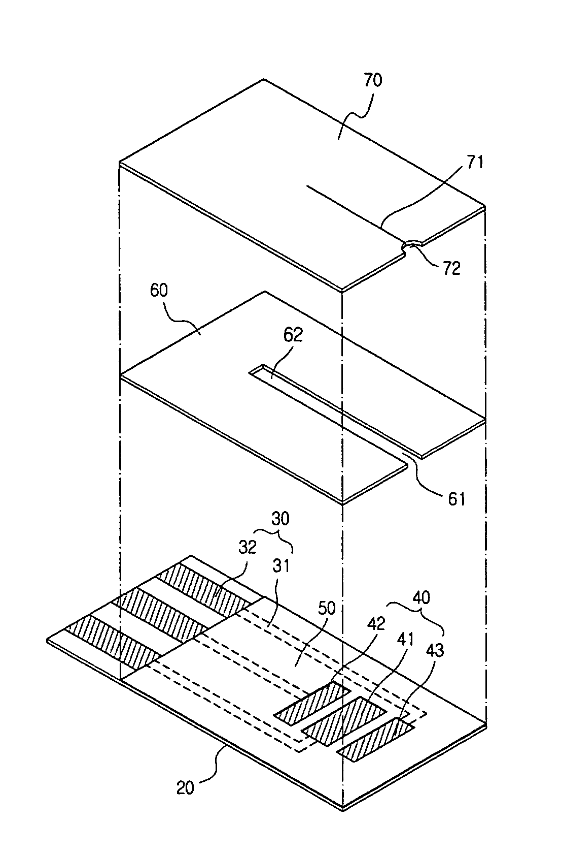
[0026]FIGS. 3a and 3b are a top view and a back view of a biosensor according to an embodiment of the present invention, respectively.

[0027]Referring to FIG. 3a, a plurality of lead terminals 31 corresponding to the number of electrodes are formed at one end of an electrically insulating base plate 20. As shown in FIG. 3b, the lead terminals 31 are connected to electrodes 41, 42 and 43, respectively, formed at the other end of the electrically insulating base plate 20 through respective lead wires 32. As shown in FIG. 3a, a slit 71 is formed at a cover 70 of the biosensor S according to the embodiment of the present invention, and extends from a curved groove 72 formed at one end of the cover 70 toward the electrodes 41, 42 and 43 to at least...


PUM

PropertyMeasurementUnit
lengthaaaaaaaaaa
electrical resistanceaaaaaaaaaa
areaaaaaaaaaaa

Abstract

A biosensor for quantifying a specific substance contained in a biological sample includes an electrically insulating base plate, a plurality of lead terminals formed on the base plate, a plurality of lead wires connected to the lead terminals, respectively, an electrode system including two working electrodes and one reference electrode connected to the lead wires, respectively, an insulating layer that insulates the electrodes, an enzyme reaction layer formed on the insulating layer and the electrodes, a spacer formed on the enzyme reaction layer so as to ensure a sufficient space that receives a sample, and a cover formed on the spacer. Further, the spacer has a sample introduction port opened at one side of the spacer, the cover has at least one slit for venting air existing in a sample receiving space defined by the spacer and the cover, and the slit extends to above the electrodes from one end of the cover.

Description

[0001]This application claims priority under 35 U.S.C. § 371 from PCT / KR02 / 01854, filed on Oct. 4, 2002 and under 35 U.S.C. § 119(a–d) from Korean patent application KR 2002 / 27971, filed on May 20, 2002.TECHNICAL FIELD[0002]The present invention relates to a sensor, and more specifically to a biosensor for quantifying a specific substance contained in a biological sample.BACKGROUND ART[0003]Generally, a biosensor comprises an electrically insulating base plate, an electrode system including a plurality of electrodes and formed on the electrically insulating base plate using a screen printing method, and an enzyme reaction layer including a hydrophilic polymer, oxidoreductase and an electron acceptor and formed on the electrode system. When a sample liquid containing a substrate is dropped on the enzyme reaction layer of the biosensor, the enzyme reaction layer is dissolved to allow the substrate and enzyme to react with each other. At a result, the substrate is oxidized, and then th...

Claims


Application Information

Patent Timeline
Patent Type & Authority Patents(United States)
IPC IPC(8): G01N27/327C12Q1/26C12Q1/00G01N33/487
CPCG01N27/3272C12Q1/001C12Q1/26
Inventor BAE, BYUNG-WOOLEE, HEON-KWONLEE, SUNG-DONGKWON, MI-JOONG
Owner INFOPIA CO LTD
Why Eureka
Try Eureka