Eureka AIR delivers breakthrough ideas for toughest innovation challenges, trusted by R&D personnel around the world.

Method for providing transverse magnetic bias proximate to a pole tip to speed up the switching time of the pole-tip during the writing operation

a technology of transverse magnetic bias and pole tip, which is applied in the field of magnetic transducers, can solve the problems of poor reliability attributes, high power consumption, and relative slow response of any mechanical system, and achieve the effect of speeding up the switching time of the pole tip

Inactive Publication Date: 2006-07-04
WESTERN DIGITAL TECH INC
View PDF9 Cites 33 Cited by
  • Summary
  • Abstract
  • Description
  • Claims
  • Application Information

AI Technical Summary

Benefits of technology

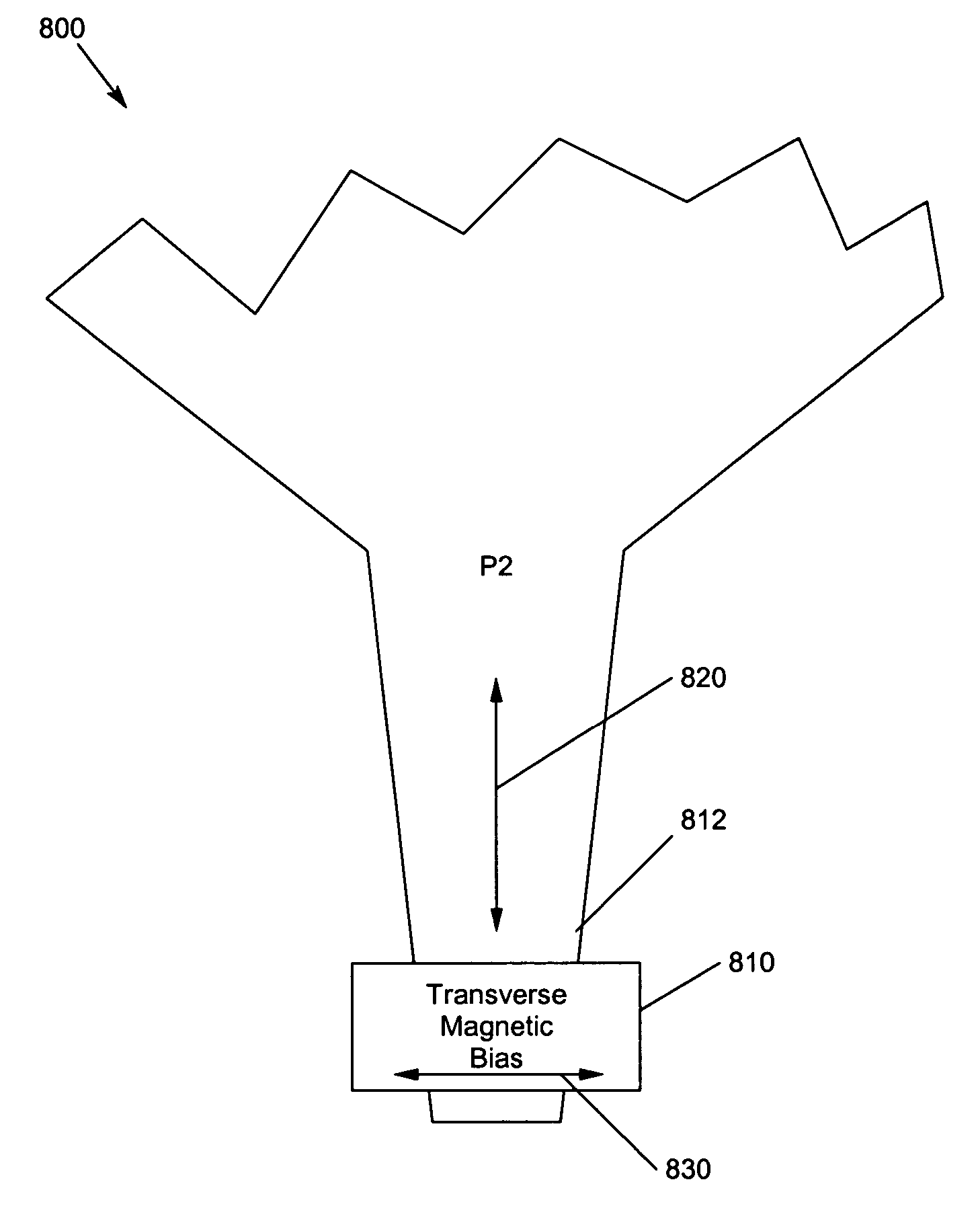
[0020]The present invention solves the above-described problems by providing a transverse field proximate the pole-tip to help the conventional driving field in rotating the magnetization through the first 90-degrees, especially at small angle where the effective anisotropy-field is strongest in opposing the conventional driving field. By offsetting the magnetization from its easy-axis, the transverse field not only decreases the initial effective anisotropy field Hk that is opposing the switching, but also increases the torque that the collinear driving field would have on the magnetization.
[0021]A method for providing assistance in magnetization switching to a pole tip in accordance with an embodiment of the present invention includes disposing a magnetic bias field source proximate to the pole tip and causing current to flow through the magnetic bias field source for providing a magnetic bias-field at a pole tip to facilitate pole-tip magnetization switching.

Problems solved by technology

In order to obtain the relatively low cost of hard disk storage compared to solid state memory, the customer must accept the less desirable features of this technology, which include a relatively slow response, high power consumption, noise, and the poorer reliability attributes associated with any mechanical system.
On the other hand, disk storage has always been nonvolatile; i.e., no power is required to preserve the data, an attribute which in semiconductor devices often requires compromises in processing complexity, power-supply requirements, writing data rate, or cost.
While nature allows us to scale down the size of each bit of information, it does not allow scaling to happen forever.
Furthermore, while these difficulties have been associated with hard disk drives, similar conclusions would apply to magnetic tape and other magnetic technologies.
Today, as the magnetic particles that make up recorded data on a hard disk drive become ever smaller, technical difficulties in writing and reading such small bits occur.
However, the present problems encountered in increasing areal density are more fundamental than problems encountered previously.
These problems include the thermodynamics of the energy stored in a magnetic bit, difficulties with head-to-disk spacings that are only an order of magnitude larger than an atomic diameter, and the intrinsic switching speeds of magnetic materials.
Unfortunately, there is no simple choice for scaling time that leaves both induced currents and electromagnetic wave propagation unchanged.
The last reason, which will ultimately cause very fundamental problems, is that the materials are not unchanged under the scaling process; we are reaching physical dimensions and switching times in the head and media at which electrical and magnetic properties are different than they were at lower speeds and at macroscopic sizes.
The problems associated with the increased data rates described above involve the switching the magnetization of the pole-tip.
Switching of the magnetization of the pole-tip at such a high data-rate, especially with the pole-tip dimensions being comparable to or even smaller than those of a single magnetic domain, is becoming a serious challenge.
However, the extra driving-field given by current-overshoot has side effects such as creating excessive erase-band, extra adjacent-track-interference (ATI), and extra protrusion.

Method used


Image

  • Method for providing transverse magnetic bias proximate to a pole tip to speed up the switching time of the pole-tip during the writing operation
  • Method for providing transverse magnetic bias proximate to a pole tip to speed up the switching time of the pole-tip during the writing operation
  • Method for providing transverse magnetic bias proximate to a pole tip to speed up the switching time of the pole-tip during the writing operation

Examples


Embodiment Construction

[0039]In the following description of the embodiments, reference is made to the accompanying drawings that form a part hereof, and in which is shown by way of illustration the specific embodiments in which the invention may be practiced. It is to be understood that other embodiments may be utilized because structural changes may be made without departing from the scope of the present invention.

[0040]The present invention provides a method for providing transverse magnetic bias proximate to a pole tip to speed up the switching time of the pole-tip during the writing operation. The transverse field disposed proximate the pole-tip helps the conventional driving field in rotating the magnetization through the first 90-degrees, especially at small angle where the effective anisotropy-field is strongest in opposing the conventional driving field. By offsetting the magnetization from its easy-axis, the transverse field also increases the torque that the collinear driving field would have o...


PUM

PropertyMeasurementUnit
magnetization switchingaaaaaaaaaa
magnetic bias fieldaaaaaaaaaa
magnetizationaaaaaaaaaa

Abstract

A method for providing transverse magnetic bias proximate to a pole tip to speed up the switching time of the pole-tip during the writing operation is disclosed. The transverse field disposed proximate the pole-tip helps the conventional driving field in rotating the magnetization through the first 90-degrees, especially at small angle where the effective anisotropy-field is strongest in opposing the conventional driving field. By offsetting the magnetization from its easy-axis, the transverse field also increases the torque that the collinear driving field would have on the magnetization.

Description

BACKGROUND OF THE INVENTION[0001]1. Field of the Invention[0002]This invention relates in general to magnetic transducers, and more particularly to a method for providing transverse magnetic bias proximate to a pole tip.[0003]2. Description of Related Art[0004]The first disk drive was introduced in the 1950s and included 50 magnetic disks that were 24-inch in diameter rotating at 1200 RPM (rotations per minute). There has been huge progress in the field of hard disk drive (HDD) technology in almost 50 years since the introduction of the first disk drive. Moreover, the rate of this progress is increasing year after year. Such success has made hard disk storage by far the most important member of the storage hierarchy in modern computers.[0005]The most important customer attributes of disk storage are the cost per megabyte, data rate, and access time. In order to obtain the relatively low cost of hard disk storage compared to solid state memory, the customer must accept the less desir...

Claims


Application Information

Patent Timeline
Patent Type & Authority Patents(United States)
IPC IPC(8): G11B5/147G11B5/00G11B5/012G11B5/02G11B5/09H01F13/00H01F17/00
CPCG11B5/00G11B5/02G11B5/09G11B5/012H01F17/0006G11B2005/0005G11B2005/0008G11B2005/0013H01F13/00G11B2005/0002
Inventor LAM, QUAN-CHIU HARRY
Owner WESTERN DIGITAL TECH INC
Why Eureka
Eureka Blog
Learn More