Methods for making microstructured polymer substrates

Inactive Publication Date: 2006-07-04
3M INNOVATIVE PROPERTIES CO
View PDF69 Cites 35 Cited by
  • Summary
  • Abstract
  • Description
  • Claims
  • Application Information

AI Technical Summary

Benefits of technology

[0012]Another method of producing unitary polymer substrates having a plurality of microfibers includes laminating two thermoplastic polymer substrates (e.g., films) to opposite sides of a template film having a plurality of microscopic holes therethrough. The template film is typically either coated with or formed from a release material such as a silicone release material. The thermoplastic polymer substrates are laminated to the template film so that a plurality of microprotrusions project from each of the thermoplastic polymer substrates into the holes and bond the two polymer substrates together through the tips of the microprotrusions. The thermoplastic polymer substrates are then delaminated from the template film while maintaining the thermoplastic polymer substrates in a sufficiently softened state to stretch the microprotrusions into microfibers prior to debonding of the thermoplastic polymer substrates from each other. Microfibers formed via this method typically have a tapered profile.
[0013]Another method which may be used to produce a unitary polymer film incl

Problems solved by technology

Current methods typically only permit the generation of polymer substrates with limited types of microstructure configurations.

Method used


Image

  • Methods for making microstructured polymer substrates
  • Methods for making microstructured polymer substrates
  • Methods for making microstructured polymer substrates

Examples


example 1

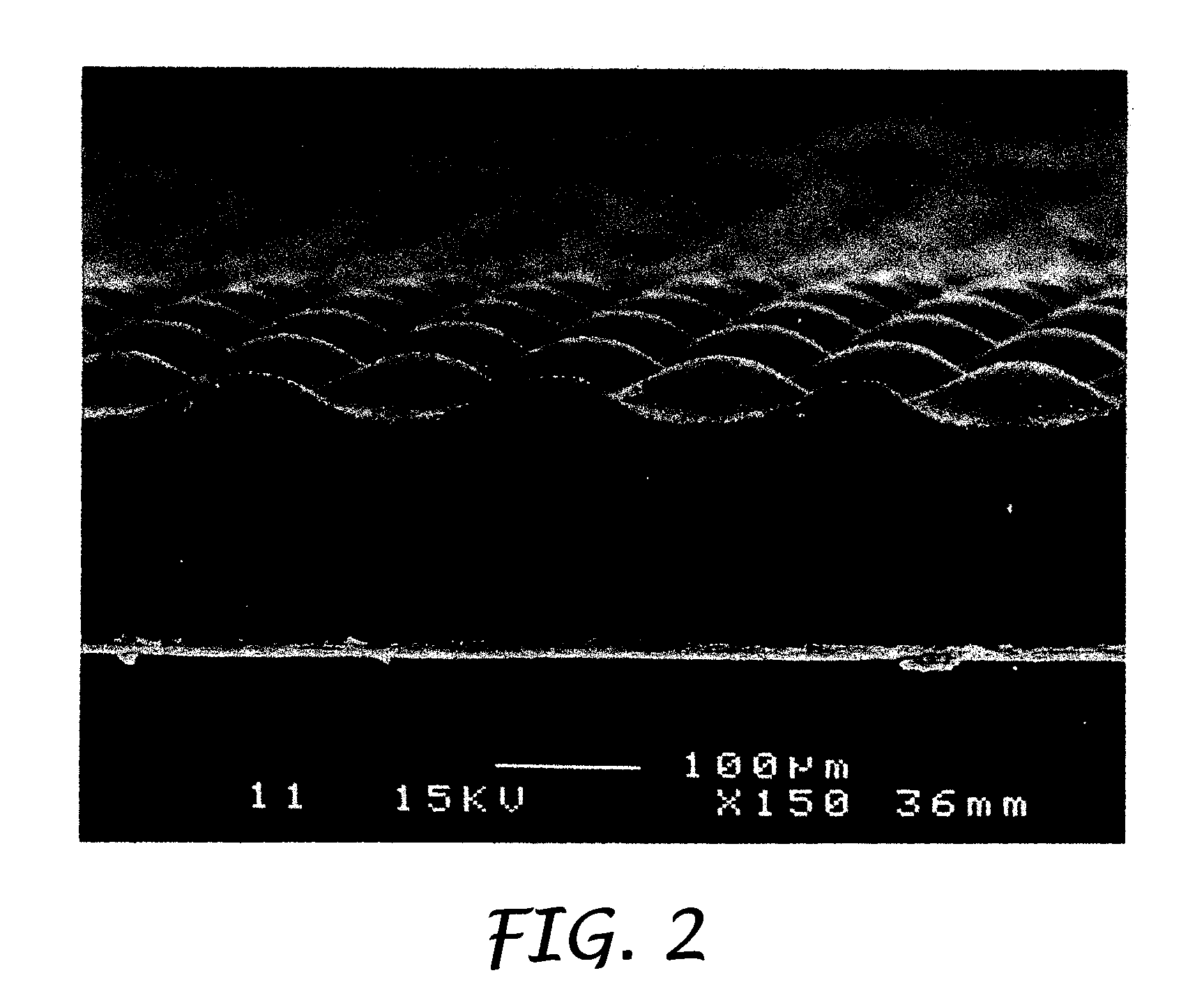
[0065]A 0.16 mm thick film of linear low density polyethylene (available from CT Films, Chippewa, Wis. under the designation X0–52; XEM 352.1) was structured on one side with features that were square at their base or intersection with the film and raised to a rounded top; the square base was about 75 μm on a side and the height was about 30 μm. The placement of the features formed a square lattice array about 0.12 mm on a side (see FIG. 2). The structured side of this film was treated with a random orbit palm sander (DeWalt Model DW 421) using 80 grit coated abrasive (80A NO-FIL ADALOX A273 available from Norton, Troy, N.Y.). Moderate hand pressure was used on the sander as it was slowly moved back and forth in a reciprocating motion in one direction for about 15 sec and then back and forth in a second direction perpendicular to the first for another 15 sec. A section was cut from the center of this sample and examined with a scanning electron microscope. Fibers with frayed tips we...

example 2

[0066]The XEM 352.1 low density polyethylene was treated as described Example 1 except that a 180 grit coated abrasive was used (P180 255L PRODUCTION RESIN BONDED FRE-CUT FILM OPEN COAT, 3M, St. Paul, Minn.). An electron micrograph of material prepared as per this example is shown in FIG. 4. The fibers formed predominately at the raised features, had lengths up to about 250 μm, were frayed at the ends and were smaller in cross section than fibers formed with the coarser grit in Example 1.

example 3

[0067]The XEM 352.1 low density polyethylene was treated as described Example 1 except that a 400 grit coated abrasive was used (P400 SG3 PRODUCTION RESIN BONDED FRE-CUT FILM OPEN COAT, 3M, St. Paul, Minn.). An electron micrograph of material prepared as per this example is shown in FIG. 5. The fibers formed at the raised features, had lengths up to about 100 μm, were frayed at the ends and were smaller in cross section than fibers formed with the coarser grits in Examples 1 and 2.


PUM

PropertyMeasurementUnit
Lengthaaaaaaaaaa
Lengthaaaaaaaaaa
Fractionaaaaaaaaaa

Abstract

A unitary polymer substrate having a plurality of microfibers projecting from a surface is provided. The presence of the microfibers greatly increases the surface area and can impart a cloth-like feel to the surface. The projecting microfibers may have a variety of forms, including frayed-end microfibers, tapered microfibers, microfibers having an expanded cross-sectional shape, and microfibers having a very high aspect ratio. A number of methods of producing unitary polymer structures with a plurality of projecting microfibers are also provided.

Description

CROSS REFERENCE TO RELATED APPLICATIONS[0001]This application is a division of U.S. patent application Ser. No. 08 / 902,172, filed Jul. 29, 1997, now U.S. Pat. No. 6,605,332.BACKGROUND OF THE INVENTION[0002]Polymer substrates with a large number of microfibers on a surface have a wide variety of potential applications. Such microstructured polymer films may be applied to a surface in order to decrease the gloss of the surface. Other surfaces which may benefit from the application of materials having increased surface area due to the presence of a large number of microfibers include carrier webs for use with adhesive tapes. Polymer surfaces covered with a plurality of microfibers also typically have a soft or cloth-like feel and can provide a low friction surface. Polymer sheet materials with smooth planar surfaces are often treated to provide fibers or fiberlike features protruding from at least one major surface. Alteration of a surface in this manner can produce a number of effects...

Claims


Application Information

Patent Timeline
IPC IPC(8): B29C41/00B28B11/08B29D7/00C08J5/18B29C59/00C08J7/00D04H11/08
CPCD04H11/08Y10T428/2978Y10T428/2976Y10T428/2973Y10T428/23957Y10T428/2395
Inventor CALHOUN, CLYDE D.KOSKENMAKI, DAVID C.BERG, JAMES G.AAMODT, JENNIFER M.
Owner 3M INNOVATIVE PROPERTIES CO
Why Eureka
Try Eureka