Membrane electrode assembly with integrated seal

a membrane electrode and integrated seal technology, applied in the field of membrane electrode assemblies, can solve the problems of excessive stress experienced in the region where the seal is located, damage and delaminate the electrode, and provide leakage paths around the edge of the mea, so as to reduce the risk of seal failure and reduce the concentration of shear stress

Active Publication Date: 2006-07-04
BALLARD POWER SYSTEMS
View PDF15 Cites 21 Cited by
  • Summary
  • Abstract
  • Description
  • Claims
  • Application Information

AI Technical Summary

Benefits of technology

[0015]The thickness of the flexible coupling is less than that of the inboard pad and is such that a gap remains between the compressing surface and the coupling when the assembly is compressed to the nominal thickness. In this way, the flexible coupling isolates the inboard pad from any stress experienced by the sealing element when the assembly is compressed to the nominal thickness.
[0016]On the other hand, the thickness of the sealing element is significantly greater than that of the inboard pad such that the compression on the sealing element is greater than that on the inboard pad when the assembly is compressed to the nominal thickness. (When compressed between the same plates, in order for the thicker sealing element to be compressed more than the thinner pad, the sealing element is substantially thicker than the pad. Unlike in the inboard pad, the resulting stress on the sealing element may exceed the electrode interface stress limit for the seal material.) Thus, even with relatively large variations in the thickness of the cell components, the sealing element can be sufficiently compressed to effect a seal when the assembly is compressed to the nominal thickness.
[0019]The integrated edge seal may also comprise additional advantageous features. For instance, the shape of the sealing element may be described by two offset circles perpendicular to the major surfaces of the membrane electrode subassembly. Such a shape allows for the application of a small amount of precompression on the sealing element without affecting its stability under load. Another useful feature is a chamfer on the inboard pad adjacent the electrode surface in order to reduce shear stress concentration at this interface and thereby reduce the risk of seal failure at this interface. Such chamfers can also serve to align and center an adjacent flow field plate when initially assembling a fuel cell stack. Yet another useful feature to include is an insulating tab adjacent the sealing element to help electrically isolate the cathode and anode flow field plates from each other at their edges.

Problems solved by technology

In previous constructions, as cell designs decrease in thickness, the stack-up of components having typical tolerance could lead to excessive stress experienced in the region where the seal attaches to the MEA (i,e., where the seal is impregnated into the porous electrodes).
The seal could then be damaged and delaminate from the electrode, thereby providing leak paths around the edge of the MEA.
Such excessive stress might occur directly from overly compressing this region or indirectly from stress transferred trough the seal material when the peripheral region of the seal is overly compressed.
In this way, the stress on the pad is insufficient to shear the pad from the saturated membrane electrode subassembly when compressed to the nominal thickness.
Thus, the pad is not directly compressed to an extent that could cause damage.

Method used


Image

  • Membrane electrode assembly with integrated seal
  • Membrane electrode assembly with integrated seal
  • Membrane electrode assembly with integrated seal

Examples


examples

[0052]In the following, conventional MEA subassemblies were employed having a NAFION® 112 electrolyte membrane and electrodes which contained gas diffusion layers made of TGP-60, and a carbon fiber paper product of Toray Industries. A silicone elastomer material was selected for use as the seal material which had similar mechanical characteristics to the aforementioned low viscosity silicones.

[0053]The interface shear stress limit for this seal material / electrode combination was determined empirically as described above. A silicone sample (4 mm square in section and 2 mm high) was cast into / onto a TGP-60 carbon fiber paper layer. Under load, the sample sheared at the interface with the carbon fiber paper at 25% compression. This corresponded to a maximum stress at the interface (or interface shear stress limit) of 1.2 MPa.

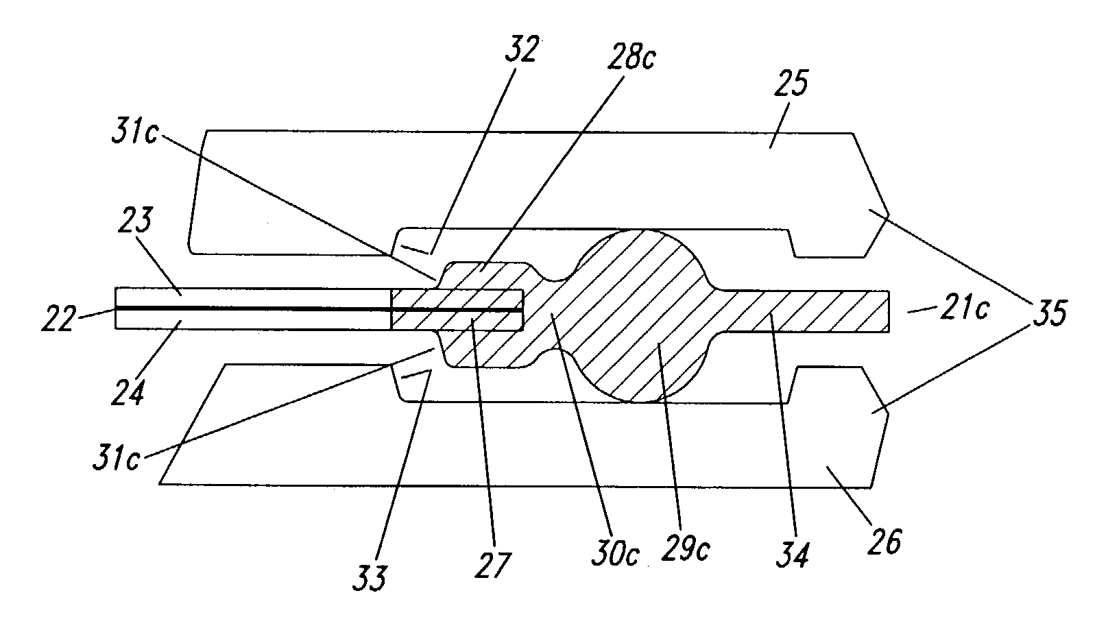
[0054]Two different MEA with integrated edge seals designs were then evaluated which employed these materials. A comparative embodiment was similar to that depicte...


PUM

PropertyMeasurementUnit
thicknessaaaaaaaaaa
thicknessaaaaaaaaaa
thickaaaaaaaaaa

Abstract

A membrane electrode assembly with an improved integrated seal comprises an edge seal having an inboard pad attached to the edge of the electrodes, a flexible coupling adjacent the pad, and a sealing element adjacent the coupling. The sealing element is significantly thicker than the pad, and the flexible coupling isolates the pad from stress experienced in the sealing element. Thus, greater compression can be applied to the sealing element, thereby providing an improved and more reliable seal, without overly compressing and damaging the attached pad.

Description

BACKGROUND OF THE INVENTION[0001]1. Field of the Invention[0002]The present invention relates to a membrane electrode assembly having a seal integrated at an edge of the assembly, as well as a solid polymer electrolyte fuel cell containing such an assembly.[0003]2. Description of the Prior Art[0004]Fuel cell systems are currently being developed for use as power supplies in numerous applications, such as automobiles and stationary power plants. Such systems offer promise of efficiently providing power with environmental and other benefits. Fuel cells convert reactants, namely fuel and oxidant, to generate electric power and reaction products. Fuel cells generally employ an electrolyte disposed between two electrodes, namely a cathode and an anode. A catalyst typically induces the desired electrochemical reactions at the electrodes.[0005]Preferred fuel cell types include solid polymer electrolyte (SPE) fuel cells that contain a solid polymer electrolyte and operate at relatively low ...

Claims


Application Information

Patent Timeline
Patent Type & Authority Patents(United States)
IPC IPC(8): H01M2/00H01M2/08H01M4/86H01M8/10
CPCH01M8/0276H01M8/1004H01M8/0284H01M4/8605Y02E60/521H01M8/248Y10T428/31797H01M8/0273Y02E60/50
Inventor ARTIBISE, ROBERT H.FARRINGTON, SIMON
Owner BALLARD POWER SYSTEMS
Why Eureka
Try Eureka