Method and circuit arrangement for generating an output voltage

a technology of output voltage and circuit arrangement, applied in the direction of ac network voltage adjustment, automatic controller, electric variable regulation, etc., can solve the problems of high current consumption of generating output voltage, and high operating current consumption of disclosed current sources

Inactive Publication Date: 2006-07-04
ATMEL GERMANY
View PDF9 Cites 9 Cited by
  • Summary
  • Abstract
  • Description
  • Claims
  • Application Information

AI Technical Summary

Benefits of technology

[0011]In a different further development of the method, the initialization is carried out by means of a time-limited initializing signal. Investigations by the applicant have shown that the operating current consumption of the circuit arrangement is not increased if the time-limited initializing signal is generated by a circuit unit that only temporarily conducts current. Especially advantageously, the generation of a time-limited initializing signal can be carried out by means of a controlled switch, of which the control input is supplied with current for only a short temporary time by means of a capacitive voltage divider.

Problems solved by technology

It is disadvantageous, that the disclosed current sources comprise a high operating current consumption and / or a high current variation of the output current for a variable input voltage.
It is disadvantageous in that context, that the band gap circuit for generating an output voltage, especially for a high input voltage range, comprises a high current consumption, which, for example, will tend to discharge the battery in applications in a motor vehicle with a switched-off ignition.
Furthermore, the demand exists to reduce the operating current consumption of such circuit arrangements due to the reduced battery capacity.

Method used


Image

  • Method and circuit arrangement for generating an output voltage
  • Method and circuit arrangement for generating an output voltage
  • Method and circuit arrangement for generating an output voltage

Examples


Embodiment Construction

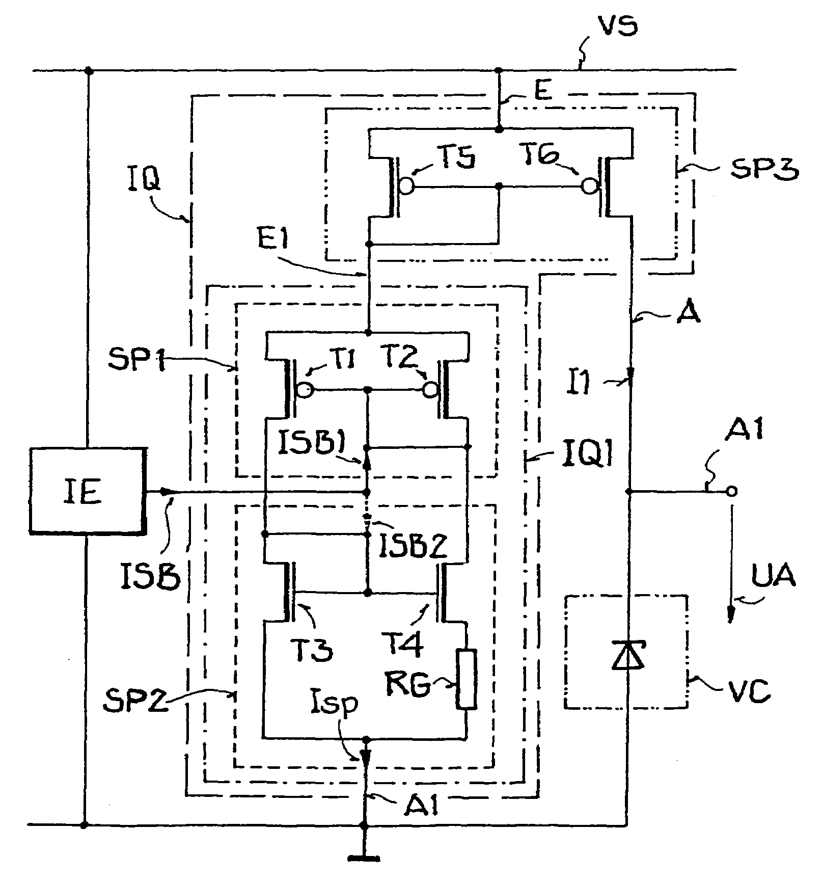
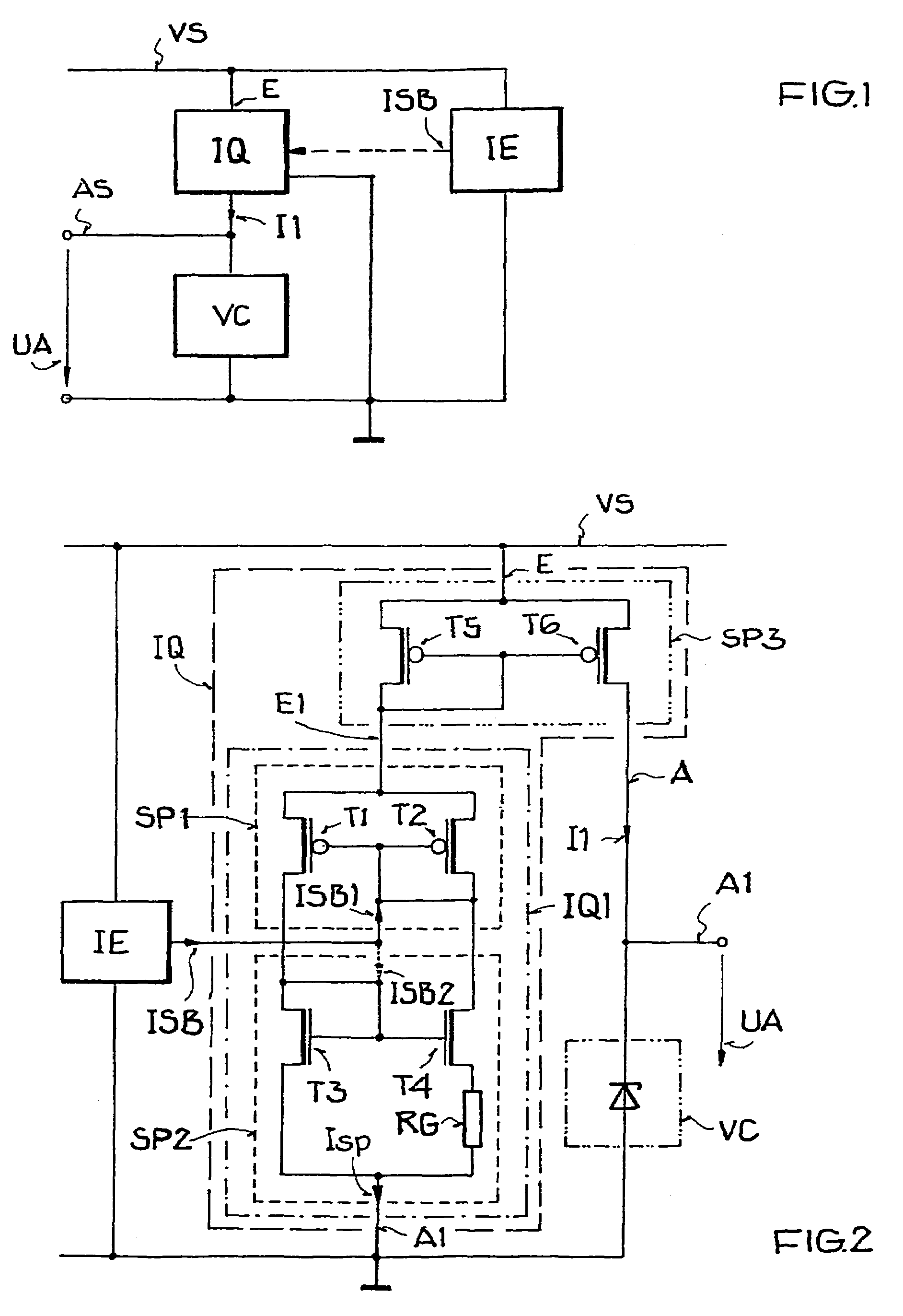
[0017]In the block circuit diagram depicted in FIG. 1, a voltage-limiting element VC is provided with current, in order to generate a stabilized output voltage UA at the output AS of the element VC. Such an output voltage UA may, for example, be utilized as a reference voltage or for driving load elements. For this, the voltage-limiting element VC is circuit-connected in series by means of a current source IQ connected with a supply voltage VS and a reference voltage preferably a ground potential. Further, the current source IQ comprises a current input E, a current output A, and an initializing input, which is connected with an initializing output ISB of an initializing unit IE. Moreover, the initializing unit IE is connected with the supply voltage VS and with the reference potential.

[0018]In the following, the functional operation of the block circuit diagram will be explained. After switching-on the supply voltage VS, a time-limited initializing signal, for example a short volta...


PUM


Abstract

An output voltage is generated, in that an initializable current source is transferred into a current-conducting state by an initializing signal produced by an initializing unit, and then provides current to a voltage-limiting element. The output voltage is tapped from the voltage-limiting element. Thereby, a small operating current consumption can be achieved with a large supply voltage range.

Description

FIELD OF THE INVENTION[0001]The present invention relates to a method and a circuit arrangement for generating an output voltage.BACKGROUND INFORMATION[0002]In general, electronic circuits are used for generating an output voltage, in order to generate a prescribed value of an output voltage for driving a load, for a prescribed value or value range of input voltages. However, such a circuit arrangement requires a reference voltage, which is generally generated by means of a diode structure, for example a Zener diode. The current through the diode structure is generally limited by means of a pre-resistance and is proportional to the magnitude of the input voltage. In order that the current through the diode structure is sufficiently large, with a variable input voltage, the pre-resistance must be dimensioned correspondingly small, that is to say, at higher input voltages, the current consumption of the circuit arrangement increases. Instead of using a pre-resistance, diode structures...

Claims


Application Information

Patent Timeline
Patent Type & Authority Patents(United States)
IPC IPC(8): G05F3/16G05F1/46
CPCG05F1/46
Inventor DRUSENTHAL, ULLRICH
Owner ATMEL GERMANY
Why Eureka
Try Eureka