Detector and lock controller using same

a technology of detector and lock controller, which is applied in the direction of electrical locking circuit, program control, anti-theft devices, etc., can solve the problems of significantly lower detection error probability of unwanted objects such as rain drops and dead leaves, and achieves relatively large detection area, improved design freedom, and operability.

Active Publication Date: 2006-07-04
OMRON AUTOMOTIVE ELECTRONICS CO LTD
View PDF8 Cites 15 Cited by
  • Summary
  • Abstract
  • Description
  • Claims
  • Application Information

AI Technical Summary

Benefits of technology

[0023]It is preferable if the aforementioned main apparatus is further adapted to send by wireless transmission another specified request signal to the portable device carried by the user when a detection output corresponding to a detection area smaller than the aforementioned one detection area of the detector is switched on while the lockable part is unlocked, to receive an answer signal from the portable device in response to the request signal, and to cause the lockable part to be locked after it is ascertained that the received answer signal is a correct signal. This embodiment is advantageous because the detector is made to function also as a trigger for the automatic locking operation. Thus, prior art button switches of the kind for the user to operate on need not be provided and the freedom in design is improved. Since the user is not required to operate on such a switch, the operability is also hereby improved.
[0024]The invention also relates to a lock controller according to another embodiment characterized not only as comprising a detector according to the third embodiment of the invention as described above and a main apparatus which is provided to a structure such as a vehicle with a lockable part such as a door having a handle and being adapted to open and close, but also wherein the main apparatus, when the lockable part in locked, is adapted to set the specified sampling timing of the wave detection circuit part so as to make the detection area relatively large, to send by wireless transmission a specified request signal to a portable device carried by the user if a detection output of the detector is switched on with the detection area made relatively large, to receive an answer signal from the portable device in response to the request signal, and to cause the lockable part to be unlocked after ascertaining that specified conditions for unlocking (including the condition that the received answer signal is a correct signal) are satisfied, and wherein the main apparatus, when the lockable part is unlocked, is adapted to set the specified sampling timing of the wave detection circuit part so as to make the detection area relatively small, to send by wireless transmission a specified request signal to the portable device carried by the user if a detection output of the detector is switched on with the detection area made relatively small, to receive an answer signal from the portable device in response to the request signal, and to cause the lockable part to be locked after ascertaining that the received answer signal is a correct signal. With such a lock controller, too, favorable effects obtainable by lock controllers according to the first embodiment of the invention can be obtained.
[0025]In the above, it is preferable if the aforementioned “specified conditions” further include condition that the detection output be switched on with the detection area made relatively small by setting the specified sampling timing of the wave detection circuit part accordingly after the detection output becomes switched on with the sampling timing of the wave detection circuit part set so as to make the detection area relatively large. With this additional condition imposed, the automatic unlocking operation is effected only when the detection outputs from a specified detection area and a smaller detection area are sequentially switched on such that it may be concluded that the user's hand is approaching the handle in a normal manner. Thus, the unlocking operation can be effected more reliably.

Problems solved by technology

For example, since the user's hand approaching the door is detected in a non-contact way by using the impulse radar technology, errors in detection due to dirt or the like do not occur and even the possibility of a detection error due to unwanted objects such as rain drops and dead leaves is significantly lower than by a conventional optical sensor.

Method used


Image

  • Detector and lock controller using same
  • Detector and lock controller using same
  • Detector and lock controller using same

Examples


Embodiment Construction

[0032]The invention is described next by way of examples with reference to the drawings.

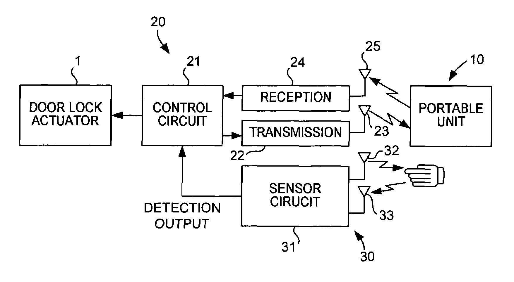
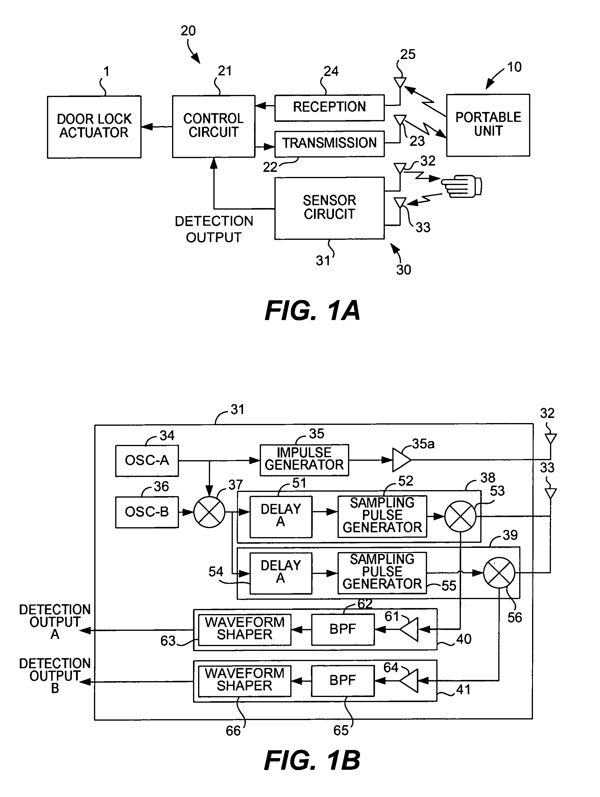
[0033]FIG. 1A shows a first embodiment of this invention as applied, for example, to a control device of a passive entry system for the door on the driver's side of a vehicle, comprising a portable unit 10, a main device 20 mounted to the vehicle and a detector 30.

[0034]Although not illustrated in FIG. 1A in detail, the portable unit 10 is provided with an antenna and a reception circuit for receiving a low frequency (LF) startup signal of about 100–150 kHz, a transmission circuit and an antenna for the wireless transmission of answer and operation (lock and unlock) signals to be described below on a high-frequency wave (say, within the UHF band), a memory (such as an EEPROM) for storing at least an identification check code (or the “ID code”), a control circuit including a microcomputer for controlling the entire operation of the portable unit 10 and battery cells.

[0035]In the above, the startup...


PUM


Abstract

A lock controller for automatically unlocking and locking a lockable part such as a vehicle door uses a detector for detecting a hand approaching inside a plurality of detection areas. Such a detector is not only arranged to transmit electromagnetic waves and to receive the reflected waves from a target object of detection such as a person's hand but also provided with a plurality of wave detection circuit parts for mixing wave detection signals corresponding to said transmission waves with signals received by said reception antenna at different sampling timings and outputting the mixed signals. A plurality of judging circuit parts each correspond to different one of the wave detection circuit parts and serve to switch on a detection output based on the outputted signals from said wave detection circuit parts to indicate that said target object is approaching and at a speed within a specified range. The detection areas have different sizes for each of the judging circuit parts corresponding to the different sampling timings of the wave detection circuit parts.

Description

BACKGROUND OF THE INVENTION[0001]This invention relates to a detector conveniently usable for detecting the user's hand as it approaches the door handle of an automobile and generating a trigger signal for initiating the automatic unlocking operation of a passive entry system for the automobile. The invention also relates to lock controllers using such a detector.[0002]In recent years, proposals are being made for vehicle entry system apparatus for automatically operating an equipment on a vehicle by carrying out two-way communications between a device carried by the user and a vehicle-mounted main device and thereby carrying out a required comparison, and some of such apparatus are actually coming to be used. With such an apparatus adapted to carry out two-way communications, an answer signal containing a necessary code can be automatically transmitted from the device carried by the user to the main device in response to a request signal (such as a startup signal for starting up th...

Claims


Application Information

Patent Timeline
Patent Type & Authority Patents(United States)
IPC IPC(8): B60R25/00B60R25/10H04Q9/00E05B49/00B60R25/01B60R25/24B60R25/31E05B81/78E05B83/36G01S13/74G01V3/12
CPCB60R25/246
Inventor MAFUNE, SHOJINEGORO, KAZUHIROSATOH, YASUHIRONISHIGUCHI, TADAO
Owner OMRON AUTOMOTIVE ELECTRONICS CO LTD
Why Eureka
Try Eureka