Image sensing apparatus and method

a technology of image sensing and image, applied in the field of image sensing apparatus and method, can solve the problems of difficult to realize a small-sized image sensing apparatus, high cost of arrangement, and difficulty in adjusting the color filter mechanism, etc., and achieve the effect of small-sized

Inactive Publication Date: 2006-07-04
CANON KK
View PDF11 Cites 63 Cited by
  • Summary
  • Abstract
  • Description
  • Claims
  • Application Information

AI Technical Summary

Benefits of technology

[0009]It is an object of the present invention to provide a small-sized and low-cost image sensing apparatus.
[0010]It is another object of the present invention to provide an image sensing apparatus with a stable light source.
[0012]The above construction makes it possible to provide an image sensing apparatus with a stable light source at a low cost. Furthermore, it also becomes possible to reduce the size of the image sensing apparatus.

Problems solved by technology

Thus, this arrangement is expensive.
Furthermore, the mechanism of switching the color filters is expensive, and it is difficult to realize a small-sized image sensing apparatus.
However, fluorescent lamps exhibit long persistence.
Furthermore, a long time is needed to stabilize the light intensity after being turned on.
As a result, a complicated circuit is needed to control the operation of turning on the fluorescent lamps

Method used


Image

  • Image sensing apparatus and method
  • Image sensing apparatus and method
  • Image sensing apparatus and method

Examples


specific embodiments

Embodiment 1

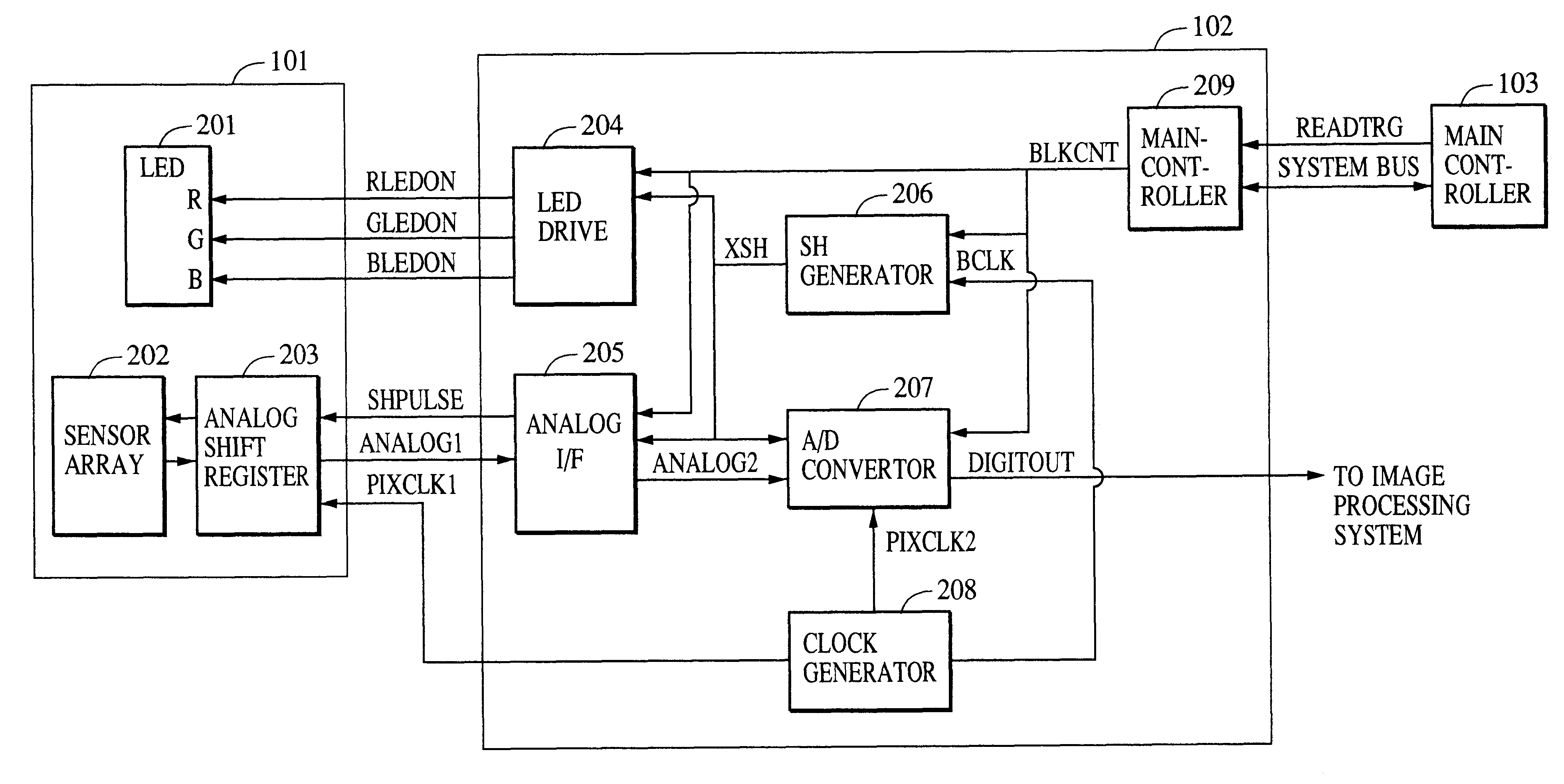
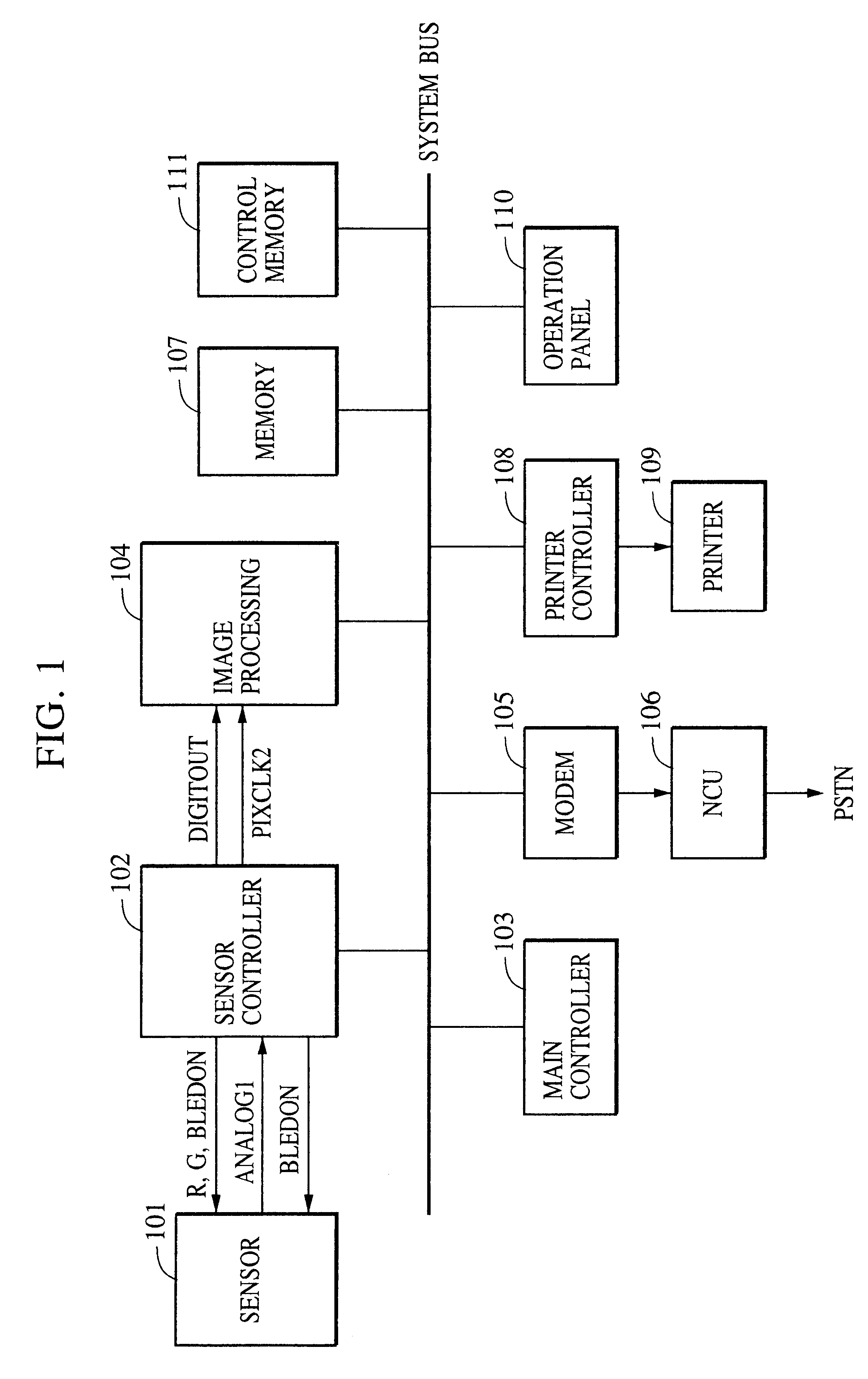
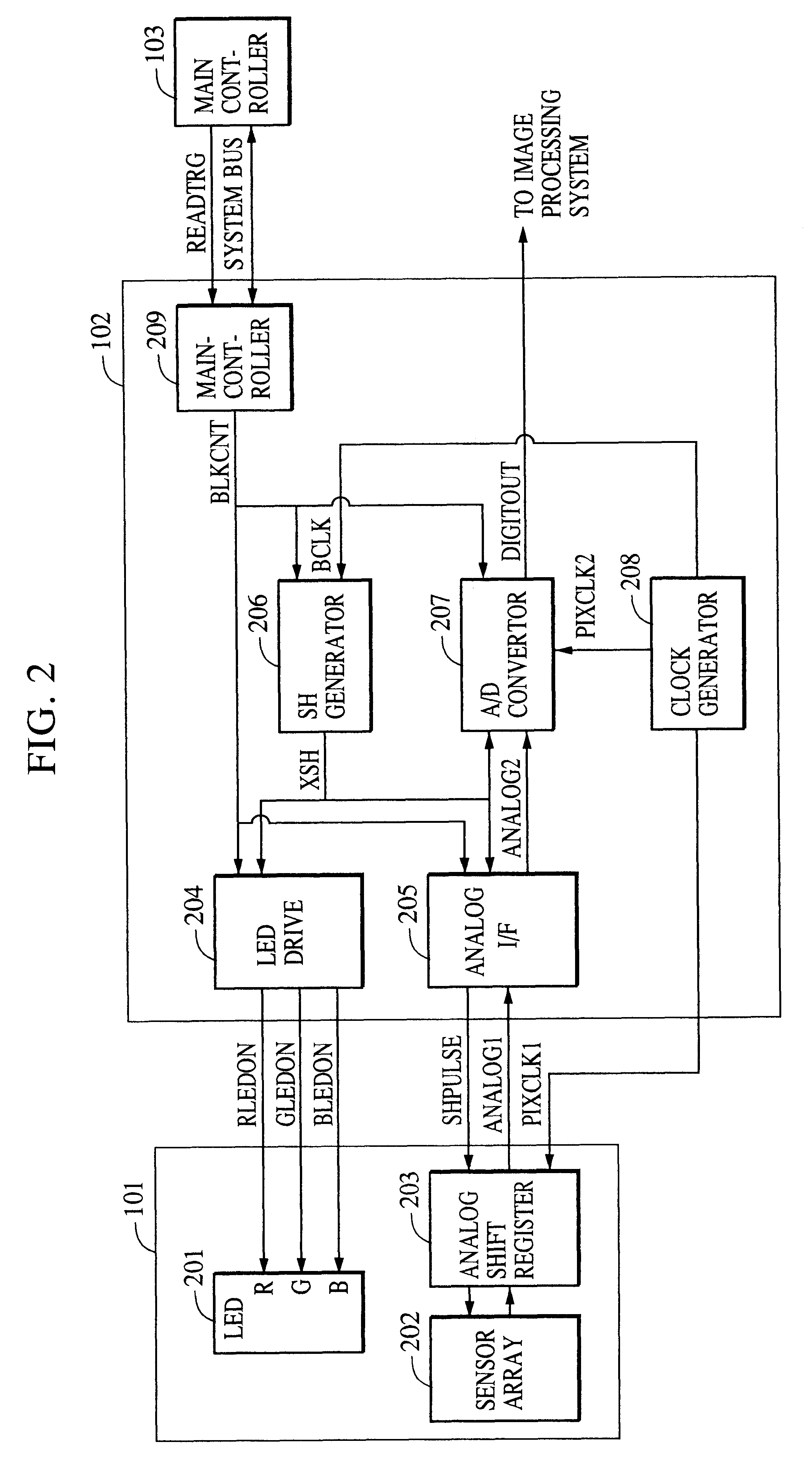
[0051]FIG. 1 is a block diagram illustrating the construction of a “facsimile” system which incorporates a first embodiment of the present invention. As shown in FIG. 1, the system includes: an image sensor 101 for converting light intensity into a corresponding electric signal; a sensor controller 102 for controlling the operation of the image sensor 101; a main controller 103 for controlling the entire parts of the image sensor system; an image processing unit 104 for performing image processing on a signal input from the sensor controller 102 and outputting a resultant signal wherein the image processing is performed in a different manner depending on a specified mode; a modem 105 for performing modulation and demodulation on data received or data to be transmitted; an NCU (network configuration utility) 106 for controlling the connection to a public switched telephone network; an image memory 107 for storing image data; a printer controller 108 for controlling the op...

embodiment 2

[0081]In this second embodiment, the LEDs are turned off during a non-sensing period. This embodiment may be achieved with hardware similar to that employed in the first embodiment described above in reference with FIGS. 1-12, and therefore the hardware is not described in further detail here.

[0082]FIG. 18 illustrates an operation sequence of switching the LEDs according to the present embodiment, for the case where the image sensing operation is paused in the middle of a color-mode operation in which the three light sources is sequentially turned on.

[0083]The red LED is turned on in an XSH period following a trigger signal READTRG and accumulation operation is performed. Therefore, an effective output analog signal is delayed by one XSH period compared to the first embodiment in which the red LED is maintained in an on-state during a non-sensing period.

[0084]In the monochrome sensing mode, the LEDs are turned off as in the color sensing mode and a particular LED specified for use i...

embodiment 3

[0089]In this third embodiment, even in a non-sensing period, LEDs are turned on in the same manner as in an image sensing period. This embodiment may also be achieved with hardware similar to that employed in the first embodiment described above and therefore the hardware is not described in further detail here.

[0090]FIG. 20 illustrates an operation sequence of switching three different LEDs so as to successively sense documents in the color sensing mode. As shown in FIG. 20, the light source LEDs are switched at intervals of one XSH in the order R, G, B.

[0091]FIG. 21 illustrates an operation sequence of switching the LEDs according to the present embodiment, for the case where the image sensing operation is paused in the middle of a color-mode operation in which the three light sources are sequentially turned on.

[0092]During the image sensing operation, the light source LEDs are switched at intervals of one XSH in the order R, G, B. Furthermore, in the present embodiment, the ligh...


PUM


Abstract

An image sensing apparatus senses an image by illuminating a document by a light source including three light emitting diodes which emit light of red, green, and blue so that the light reflected from the document is incident on a sensor array which in turn generates an electric signal corresponding to the incident light, wherein a predetermined light emitting diode is also turned on during a period in which no image sensing operation is performed thereby making it possible to stabilize the intensity of light illuminating an image. Thus, the invention provides a high-performance and small-sized image sensing apparatus at a low cost.

Description

BACKGROUND OF THE INVENTION[0001]1. Field of the Invention[0002]The present invention relates to a novel an image sensing apparatus for use in a color facsimile device, color copying apparatus, color scanner, or similar devices and to a novel method for sensing color images.[0003]2. Description of the Related Art[0004]In the art, the following three arrangements are known for sensing a color image:[0005]a) A single light source, such as a xenon lamp, and color photoelectric conversion devices, each having its own color filter formed on its surface;[0006]b) A single light source, such as a xenon lamp, and a color photoelectric conversion device in conjunction with a plurality of mechanically switched color filters; and[0007]c) Three light sources such as fluorescent lamps which emit light of R, G, and B (red, green and blue), and which are switched during an image sensing operation.[0008]These known arrangements have the following problems. When the arrangement (a) used to sense a co...

Claims


Application Information

Patent Timeline
Patent Type & Authority Patents(United States)
IPC IPC(8): H04N7/18H04N9/04H04N1/04H01L31/0232H04N1/48
CPCH04N1/484
Inventor OHTANI, ATSUSHIUENO, YASUHIDEKIMURA, MASASHI
Owner CANON KK
Why Eureka
Try Eureka