Switching power source circuit for independent per cycle control of ON/OFF time ratio

a power supply circuit and per cycle control technology, applied in the direction of electric variable regulation, process and machine control, instruments, etc., can solve the problems of insufficient feedback control loop, response delay and excessive response, and contrivance is not fundamentally problem-solving

Inactive Publication Date: 2006-07-04
FDK CORP
View PDF19 Cites 61 Cited by
  • Summary
  • Abstract
  • Description
  • Claims
  • Application Information

AI Technical Summary

Benefits of technology

[0012]The present invention was made in view of the above-described problems, and one of objects of the present invention is to provide a switching power supply circuit capable of responding to a rapid and large change in the load quickly and stably and ensuring a power supply output having a predetermined voltage.

Problems solved by technology

When a load current changes rapidly and greatly like, for example, a local power supply for use in a CPU of a personal computer, the foregoing feedback control loop can not sufficiently follow the change in the load, and a so-called response delay and an excessive response occur.
However, in order to adopt such contrivance, a large-scale capacitor having a capacity large enough to fully absorb the change in the load current is required, and this contrivance is not fundamental problem-solving means.
For example, though a recent high-speed CPU is designed to consume a large current with a low voltage, there is a problem in that the smoothing capacitor alone is allowed to absorb a current change in a low impedance load as described above.
On the other hand, when a response speed is increased to cope with the rapid change of the load in the foregoing conventional switching power supply circuit, a problem occurs in which a loop operation of the feedback control becomes unstable and troubles such as oscillation are apt to occur.

Method used


Image

  • Switching power source circuit for independent per cycle control of ON/OFF time ratio
  • Switching power source circuit for independent per cycle control of ON/OFF time ratio
  • Switching power source circuit for independent per cycle control of ON/OFF time ratio

Examples


first embodiment

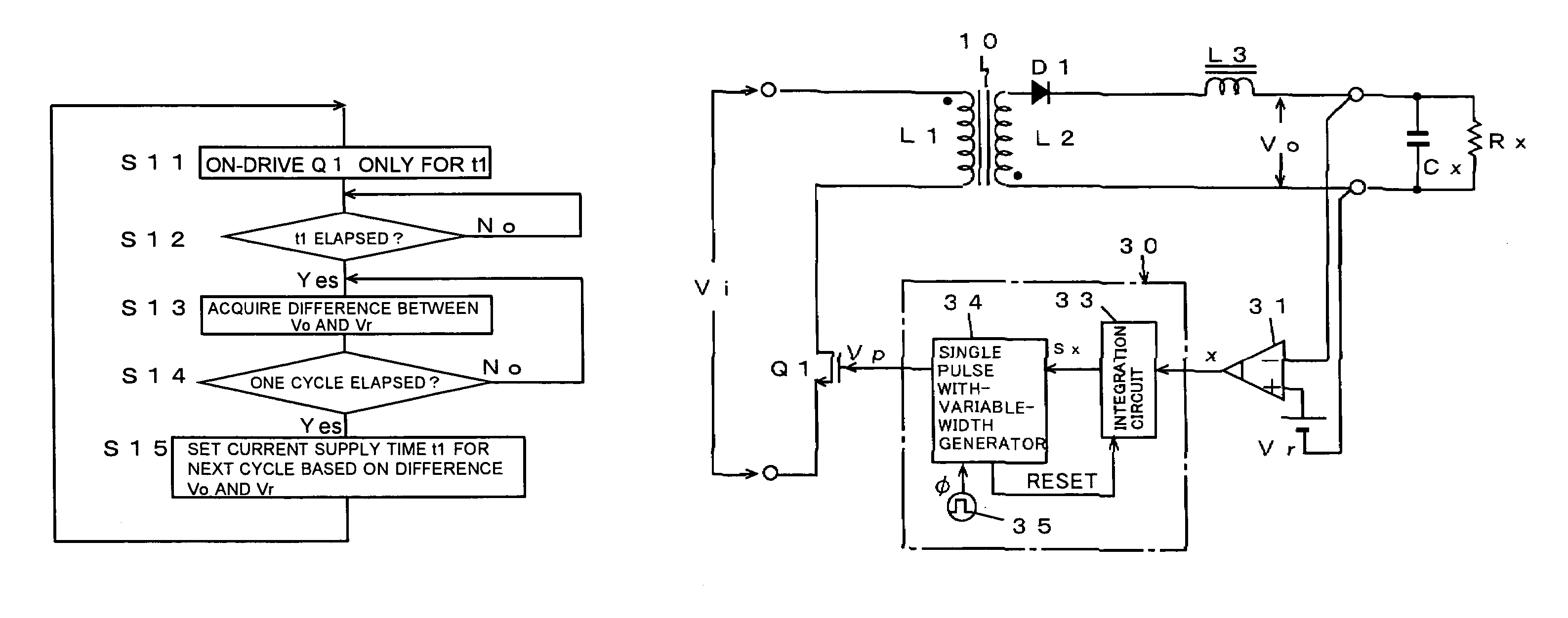
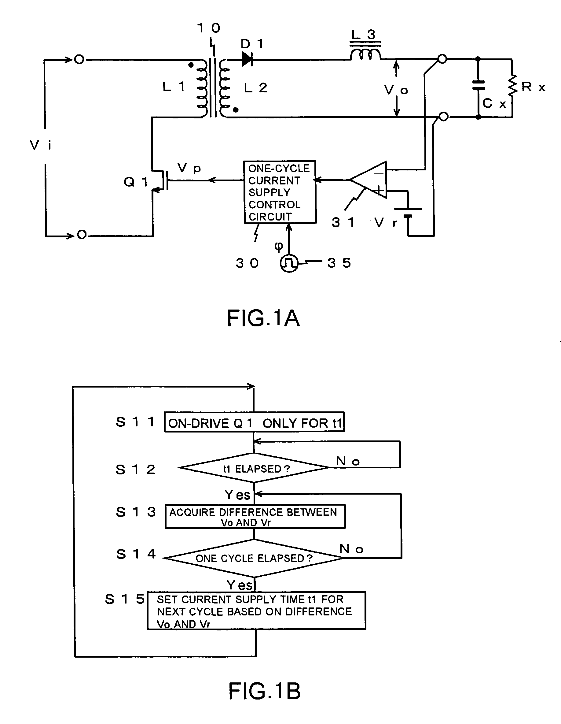
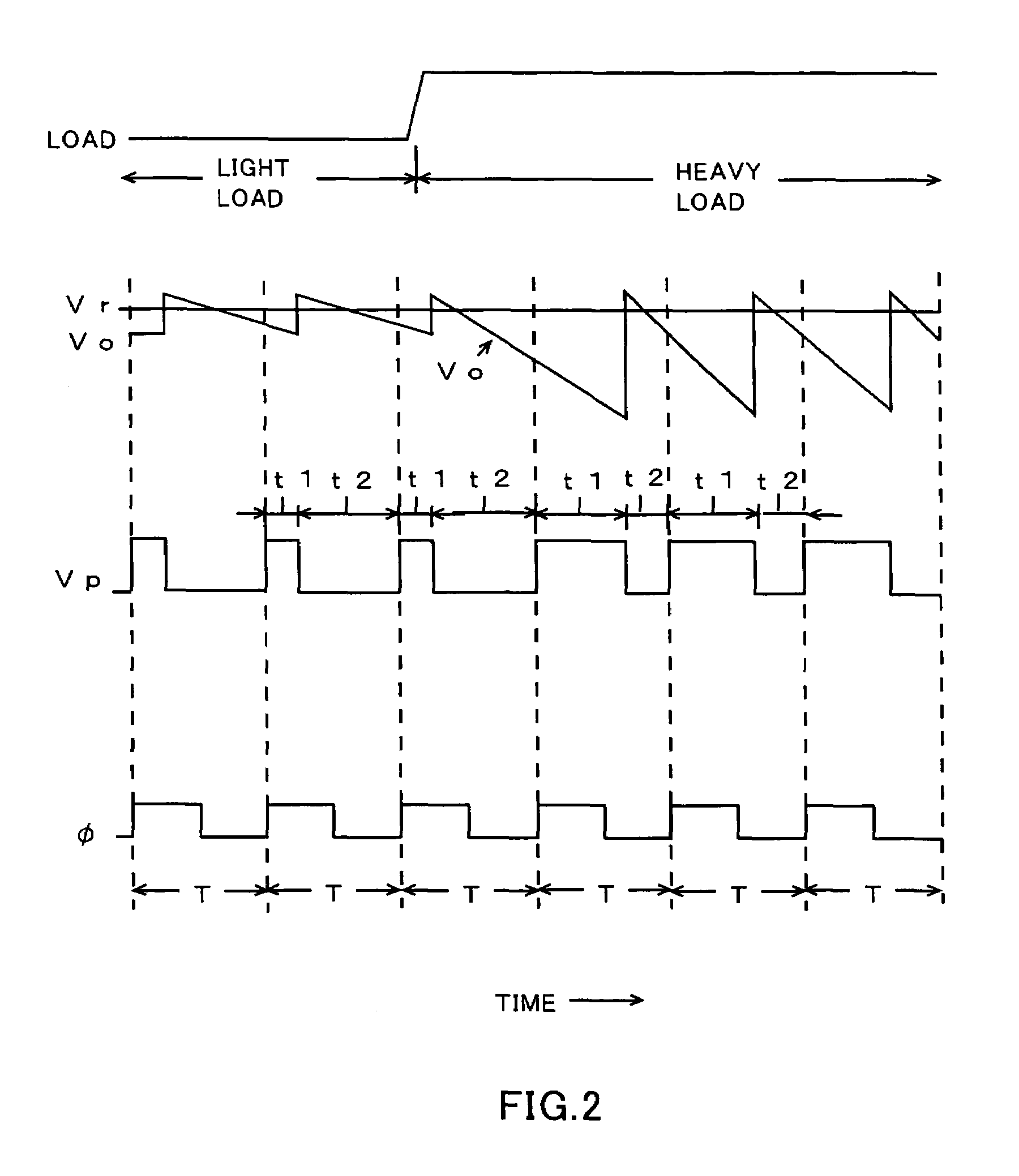
[0036]FIGS. 1A and 1B illustrate a switching power supply circuit according to the present invention. FIG. 1A shows a circuit diagram of a principal part of the switching power supply circuit, and FIG. 1B shows a flow chart illustrating an operation of the principal part thereof. FIG. 2 shows a waveform chart illustrating an operation in the principal part of the circuit of FIG. 1A.

[0037]The switching power supply circuit illustrated in the figures is constituted with use of a power MOS transistor Q1 as a switching element, a high frequency power transformer 10, a diode D1, a choke coil L3, a one-cycle current supply control circuit 30 serving also as a driving circuit for the switching element, a voltage comparison circuit 31, a clock generator 35, and the like as shown in FIG. 1A. In this case, the choke coil L3 is equivalently formed by an inductance which is not coupled to a power transformer, and an inductance distributed or parasitized on a current line or the like.

[0038]In th...

second embodiment

[0044]FIG. 3A show the switching power supply circuit according to the present invention. FIG. 3A shows a circuit diagram of a principal part thereof, and FIG. 3B shows a waveform chart of an operation thereof.

[0045]This second embodiment is a more specified example of the foregoing first embodiment, and an integration circuit 33 and a single pulse with-variable-width generator 34 are used in order to constitute the foregoing one-cycle current supply control circuit 30.

[0046]The voltage comparison circuit 31 for detecting a control error outputs a difference between an output voltage Vo and a reference voltage Vr in the form of a binary logic level of high and low levels. Specifically, when the output voltage Vo, that is, a control value, falls below the reference voltage Vr, that is, a target value, the voltage comparison circuit 31 outputs an active level of high. When the output voltage Vo exceeds the reference voltage Vr, the comparison circuit 31 outputs an inactive level of lo...

third embodiment

[0048]FIGS. 4A and 4B show the present invention. Respectively, FIG. 4A shows a circuit diagram of a principal part thereof, and FIG. 4B shows a waveform chart of an operation thereof.

[0049]A switching power supply circuit of the third embodiment is constituted so that while an input current, which is supplied thereto at the time when a power MOS transistor Q1 is made to be turned on, is accumulated in a coil L4, an inertial current (shown by the dotted line with arrow) flowing through the coil L4 at the time when the transistor is made to be turned off is rectified by a diode D1 to be charged in a capacitor C1, whereby an output voltage Vo is taken out from the capacitor C1. A so-called back converter-type switching power supply circuit is constituted.

[0050]In this embodiment, as in the case of the foregoing second embodiment, a current supply time t1 of each current supply cycle T is variably set with use of a voltage comparison circuit 31 which outputs a difference between an out...


PUM


Abstract

A switching power supply circuit, which can respond to a rapid and large change in a load quickly and stably and ensure a power supply output having a predetermined voltage, is provided. In the power supply circuit which supplies an input current to a load while switching the input current periodically and controls an output voltage Vo supplied to the load to a predetermined target value by controlling an ON / OFF time ratio (t1 / t2) of the switching variably, a control of the ON / OFF time ratio is performed for every one current supply cycle T independently.

Description

CROSS-REFERENCE TO RELATED APPLICATIONS[0001]This application is a continuation of the International Application No. PCT / JP03 / 05194 filed on Apr. 23, 2003 designating the United States of America.BACKGROUND OF THE INVENTION[0002]1. Field of the Invention[0003]The present invention relates to a switching power supply circuit, and more particularly to a switching power source circuit which is effectively applied to, for example, a voltage stabilizing power supply, a DC voltage converter and the like.[0004]2. Description of the Related Art[0005]A switching power supply circuit supplies an input current to a load while switching the input current periodically, and variably controls an ON / OFF time ratio of the switching, whereby the switching power supply circuit controls an output voltage supplied to the load to a predetermined target value. In recent years, this switching power supply circuit has come to be widely used for a local power supply for use in a CPU of a personal computer, a...

Claims


Application Information

Patent Timeline
Patent Type & Authority Patents(United States)
IPC IPC(8): H02M3/335G05F1/40H02M3/28H02M3/137H02M3/156
CPCH02M3/156H02M3/33507Y02B70/16H02M2001/0032H02M1/0032Y02B70/10
Inventor NAKAO, FUMIAKISUZUKI, TETSUYAYAMASHITA, YASUOTAKEHARA, KAZUO
Owner FDK CORP
Why Eureka
Try Eureka