
Method and apparatus for generating multi-level reference voltage in systems using equalization or crosstalk cancellation

a reference voltage and multi-level technology, applied in the field of electric buses, can solve the problems of voltage only being pulled down from the vsub>term, different amounts of signal loss, and the ability of the receiving device to distinguish binary signals

Inactive Publication Date: 2006-07-04
RAMBUS INC
View PDF29 Cites 44 Cited by
  • Summary
  • Abstract
  • Description
  • Claims
  • Application Information

AI Technical Summary

Benefits of technology

[0014]A multi-level driver uses multiple pulse amplitude modulation (multi-PAM) output drivers to send multi-PAM signals. A multi-PAM signal has two or more voltage levels, with each data interval now transmitting a “symbol” at one of the valid voltage levels. In one embodiment, a symbol represents two or more bits. The multi-PAM output driver drives an output symbol on a signal line. The output symbol preferably represents at least two bits that include a most significant bit (MSB) and a least significant bit (LSB). A multi-PAM receiver receives the output symbol from the signal line and determines the MSB and the LSB.
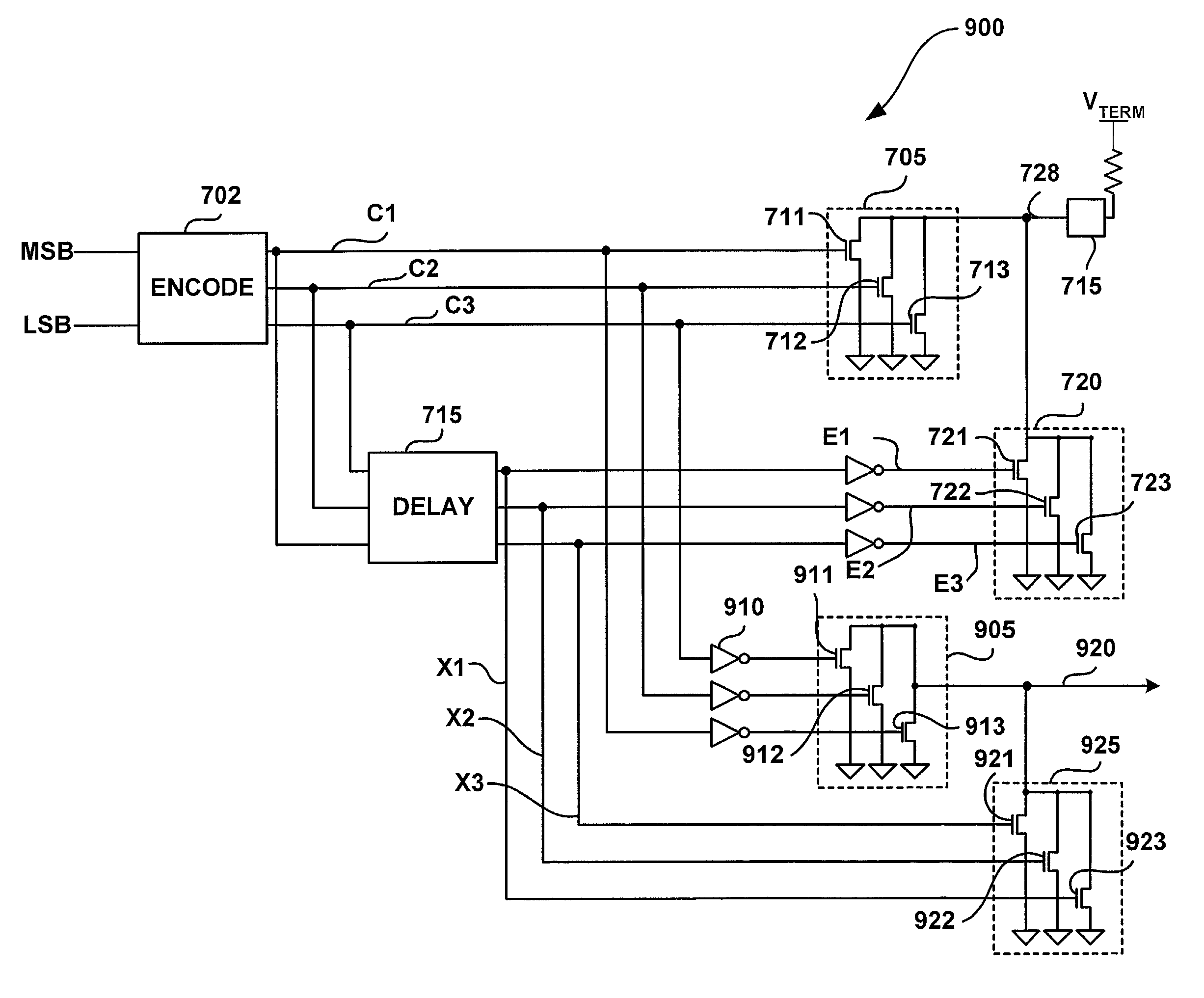
[0015]In accordance with one aspect of the invention, a reference voltage generator for a driver, such as a current driver, is provided. The current driver includes at least one reference voltage level, at least one current control signal, and at least one active device coupled to a selected reference voltage level of the at least one reference voltage level and the at least one current control signal. The active device shifts the at least one reference voltage level based on the at least one current control signal such as an equalization signal or a crosstalk cancellation signal. In one embodiment, the current driver is arranged to operate in a 2-PAM mode, a 4-PAM mode, or an N-PAM mode.
[0016]In accordance with another aspect of the invention, a method for generating a plurality of reference voltage levels for a driver is provided. The method includes providing at least one reference voltage level, providing at least one current control signal, and adjusting the at least one reference voltage level based on the at least one current control signal. In one embodiment, the at least one reference voltage level is generated on a resistive voltage divider or a reference voltage driver. Further, the at least one current control signal may include, for example, an equalization current control signal or a crosstalk cancellation signal.
[0017]These as well as other aspects and advantages of the present invention will become more apparent to those of ordinary skill in the art by reading the following detailed description, with reference to the accompanying drawings.

Problems solved by technology

However, at higher frequencies, receiving devices may have a reduced ability to distinguish binary signals.
Further, for cases in which attenuation of a signal exists between transmission and reception, different amounts of signal loss may occur depending upon the magnitude of transition between logic states.
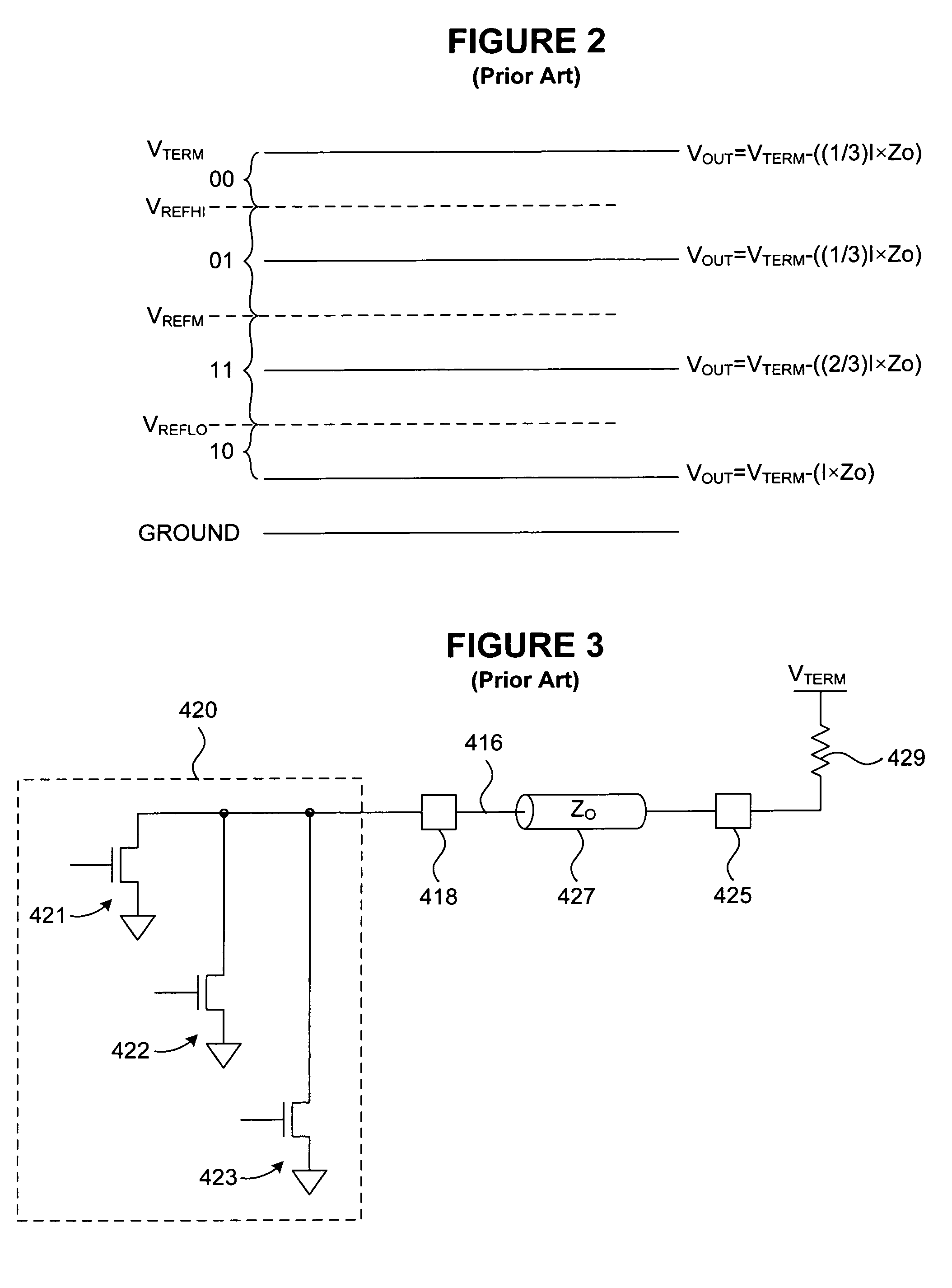
However, a difficulty with this approach for a typical multi-PAM system is that the voltage can only be pulled down from the VTERM, unless negative current could flow through current sources.
This may cause the respective reference voltages to be no longer centered on the shifted data eyes.
As is known in the art, crosstalk is a disturbance caused by the electric or magnetic fields of one telecommunication signal and impairs signals on adjacent signal lines.

Method used


Image

  • Method and apparatus for generating multi-level reference voltage in systems using equalization or crosstalk cancellation
  • Method and apparatus for generating multi-level reference voltage in systems using equalization or crosstalk cancellation
  • Method and apparatus for generating multi-level reference voltage in systems using equalization or crosstalk cancellation

Examples


Embodiment Construction

)

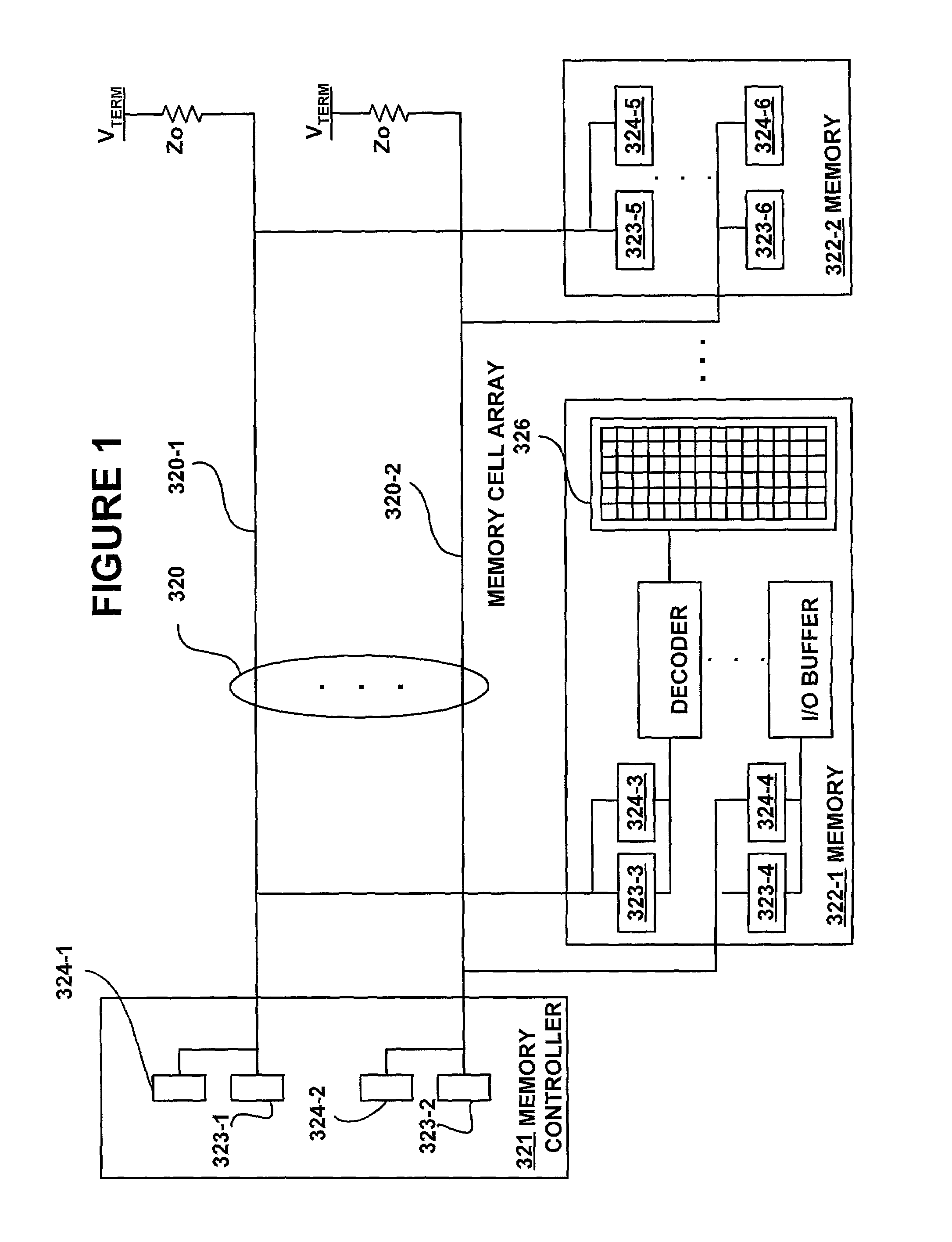
[0042]In FIG. 1, a bus 320 interconnects a memory controller 321 and memories 322. The bus 302 is formed of signal lines 320-1, 320-2 that transmit address, data and control signals. Physically, on each integrated circuit 321, 322, the address, data and control signals are supplied to and output from external connections, called pins, and the bus 320 interconnects respective pins. The bus 320 may be implemented as traces on a printed circuit board, wires or cables and connectors. Each of these integrated circuits 321, 322 has bus output driver circuits 323 that connect to the pins to interface with the bus 320 to transmit signals to other ones of the integrated circuits. In particular, the bus output drivers 323 in the memory controller 321 and in the memories 322 transmit data over the bus 320. Each bus output driver 323 drives a signal line of the bus 320. For example, bus output driver 323-1 in the memory controller 321 drives bus line 320-1. The bus 320 supports signaling with ...


PUM


Abstract

A system and method are shown for generation of at least one reference voltage level in a bus system. A reference voltage generator on a current driver includes at least one reference voltage level, at least one control signal, and an active device. The active device is coupled to the at least one control signal, such as a current control signal, and a selected reference voltage of the at least one reference voltage level. The active device is arranged to shift the at least one reference voltage level based on the at least one current control signal such as an equalization signal, a crosstalk signal, or the combination thereof, employed on the current driver.

Description

CROSS REFERENCE TO RELATED APPLICATION(S)[0001]This application is a continuation-in-part of U.S. patent application Ser. No. 09 / 654,643, entitled “Low Latency Equalization in Multi-Level, Multi-Line Communication Systems,” filed Sep. 5, 2000, and, is continuation-in-part of U.S. patent application Ser. No. 09 / 655,010, entitled “Method and Apparatus for Calibrating a Multi-Level Current Mode Driver,” filed on Sep. 5, 2000, now U.S. Pat. No. 6,772,351 which claims priority to U.S. Provisional Patent Application Ser. No. 60 / 158,189, entitled “A Method and Apparatus for Receiving High Speed Signals with Low Latency,” filed on Oct. 19, 1999, the contents of each of which are incorporated herein by reference. Further, this application claims priority to a PCT Application No. PCT / US01 / 27478, entitled “Method and Apparatus for Calibrating a Multi-Level Current Mode Driver and for Generating a Multi-Level Reference Voltage in Systems Using Equalization or Crosstalk Cancellation,” filed on S...

Claims


Application Information

Patent Timeline
Patent Type & Authority Patents(United States)
IPC IPC(8): H04L25/34H04L25/49G11C7/10H04L7/033H04L25/02H04L25/03H04L25/08
CPCG11C7/1051G11C7/1057G11C7/106G11C7/1078G11C7/1084G11C7/1087H04L25/4902H04L25/0282H04L25/03019H04L25/03878H04L25/08H04L25/0272H04L7/0332
Inventor ZERBE, JAREDWERNER, CARL
Owner RAMBUS INC
Learn More