

Reflection type mask
- Summary
- Abstract
- Description
- Claims
- Application Information
AI Technical Summary
Benefits of technology
Problems solved by technology
Method used
Image

Examples
first embodiment
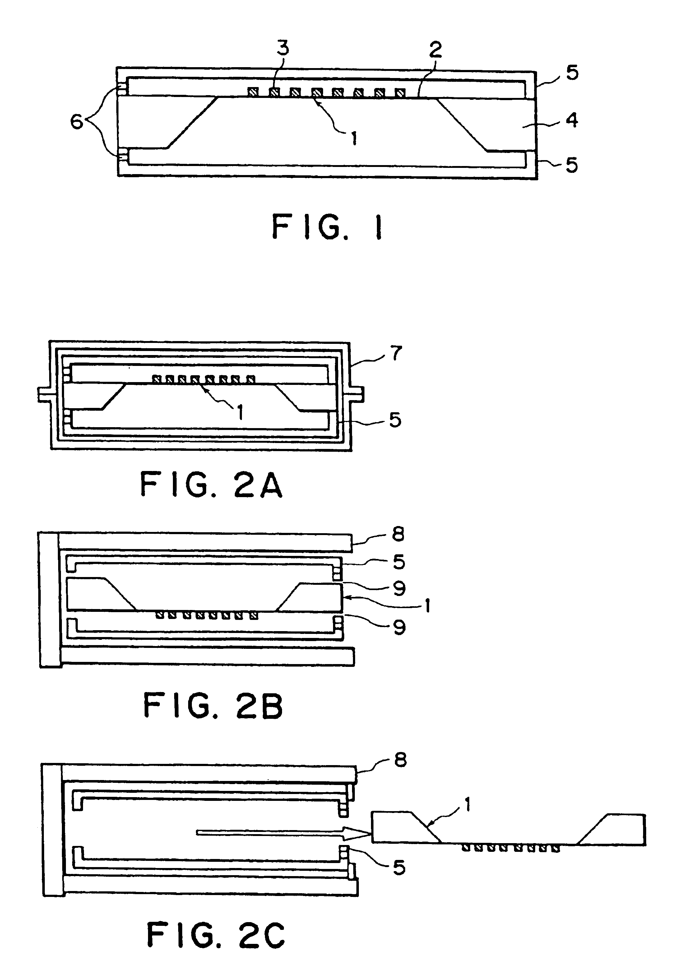
[0038]FIG. 1 is a side view showing the arrangement of the first embodiment of an X-ray mask according to the present invention. FIGS. 2A to 2C depict the states in the use of the X-ray mask and mask pattern protection members shown in FIG. 1, in which FIG. 2A is a side view in the storage state, FIG. 2B is a side view in the preparation state in which the X-ray mask is unloaded, and FIG. 2C is a side view upon unloading the X-ray mask.
[0039]Referring to FIG. 1, an X-ray mask 1 used in this embodiment is a transmission type X-ray mask in which an Au mask pattern 3 serving as an absorber for absorbing X-rays is formed on a 2-μm thick SiC membrane 2 having an Si substrate as a support member 4.
[0040]Mask pattern protection members 5 are set on both surfaces of the X-ray mask 1 after defect inspection of the X-ray mask 1 to form a dust-proof space. Each mask pattern protection member 5 is formed of a 1-mm thick plastic plate subjected to an antistatic treatment. Since the mask pattern ...
second embodiment
(Second Embodiment)
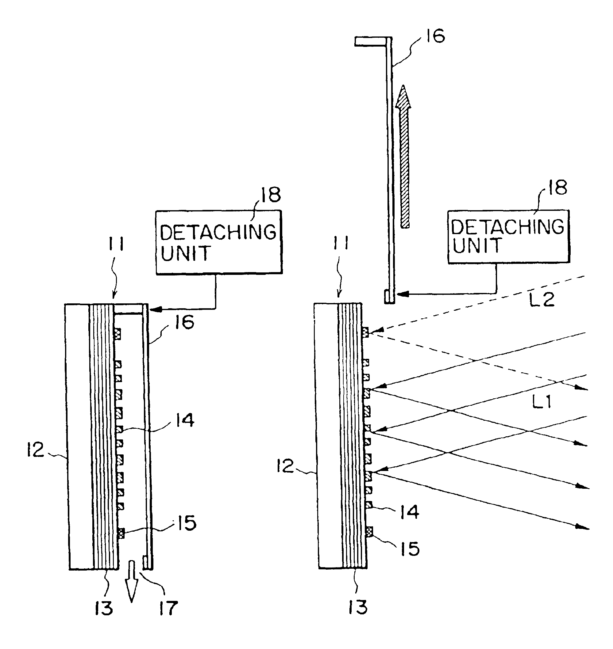
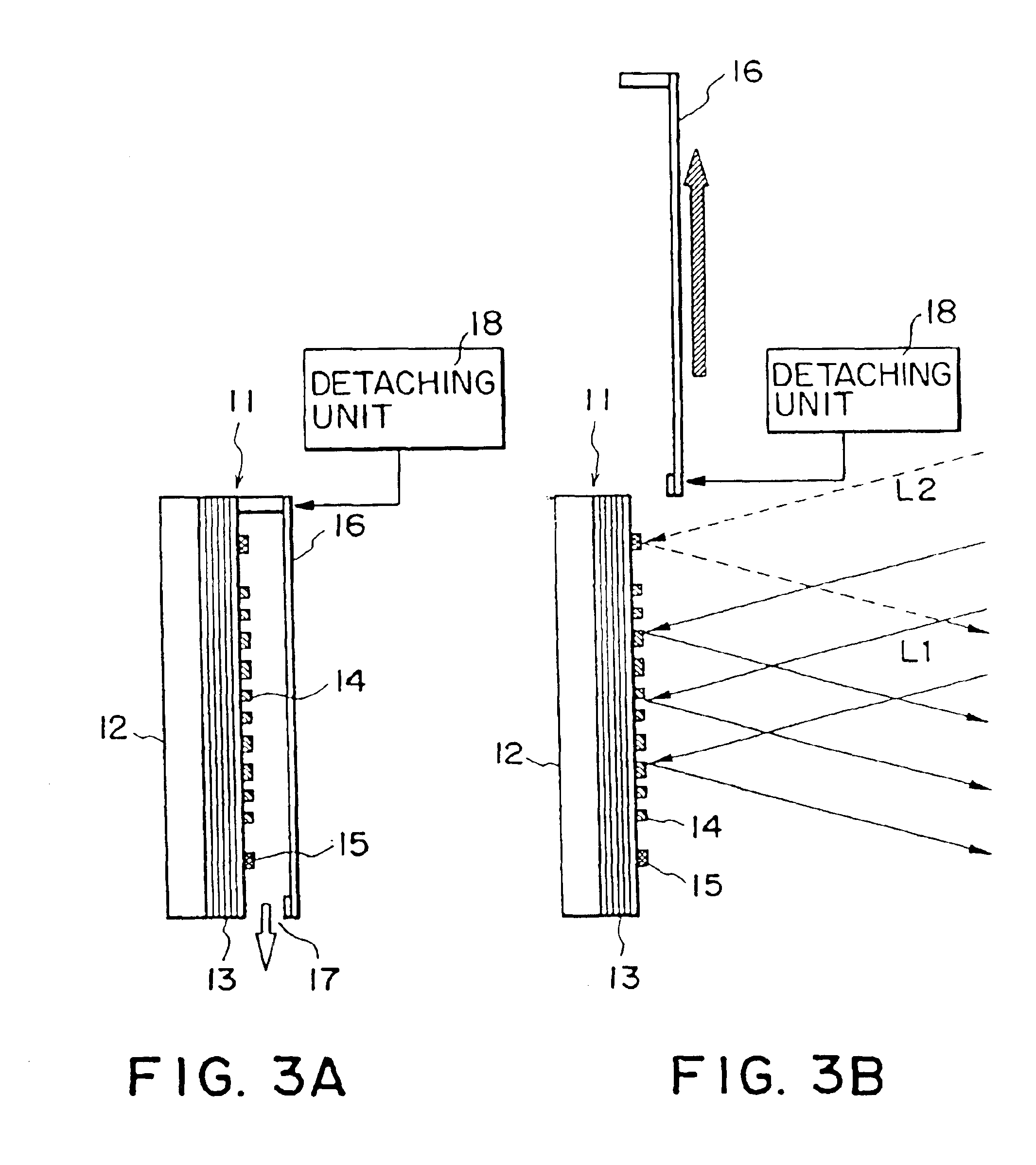
[0052]FIGS. 3A and 3B show the arrangement of the second embodiment of an X-ray mask according to the present invention, in which FIG. 3A is a side view of the mask attached with a mask pattern protection member, and FIG. 3B is a side view showing the state wherein the mask pattern protection member is retreated from the optical paths of exposure light and alignment light.
[0053]An X-ray mask 11 used in this embodiment is a reflection type mask, in which a Cr—C multilayered film reflection layer 13 is formed on an SiC substrate 12, and a mask pattern 14 is formed on the layer 13 by patterning an Au layer that absorbs X-rays to have a desired pattern.
[0054]Combinations of materials, film thicknesses, and the like of the reflection layer 13 of the reflection type mask are appropriately selected in correspondence with the wavelength used. Typical combinations of the materials include: Mo—Si, W—Si, and the like (in the vicinity of a wavelength of 13 mm); or W—C, Ni—C, ...
third embodiment
(Third Embodiment)
[0070]The third embodiment of the present invention will be described below. In the third embodiment, a reflection type mask similar to that in the second embodiment is used, and vent holes have lids which are free to open / close.
[0071]FIGS. 4A to 4C show the arrangement of the third embodiment of an X-ray mask according to the present invention, in which FIG. 4A is a side view showing the storage state, FIG. 4B is a side view showing the state inside a preliminary evacuation chamber, and FIG. 4C is a side view showing the state upon alignment adjustment and exposure.
[0072]Referring to FIG. 4A, a mask pattern protection member 26 for protecting a mask pattern 23 is attached onto an X-ray mask 21, and vent holes 27 with lids 28 are formed on the side surfaces of the mask pattern protection member 26. Each lid 28 is biased by a spring to close so as to prevent foreign matter from entering via the vent hole 27 when the mask 21 is present outside the exposure apparatus....
PUM
 Abstract
Description
Claims
Application Information