Optically coupled headset and microphone

a technology of optically coupled headsets and microphones, applied in the field of optically coupled headsets and/or microphones, can solve the problems of degrading the audio signal going to the headset, affecting the front-end electronics of the equipment side, affecting the audible communication, etc., so as to reduce the current and voltage induced, the effect of improving audible communication

Inactive Publication Date: 2006-07-04
SPRING SPECTRUM LP
View PDF14 Cites 104 Cited by
  • Summary
  • Abstract
  • Description
  • Claims
  • Application Information

AI Technical Summary

Benefits of technology

[0006]It is therefore desirable to provide an non-electrical connection between the electronic equipment and the headset and/or microphone that reduces induced currents and voltages due to external radio-frequency sources. The non-electri...

Problems solved by technology

An electrical coupling such as conductive wires, however, may introduce interference that degrades the audio signals.
External radio-frequency (“RF”) sources may induce interference into an electrical coupling.
The induced currents degrade the audio signals going to the headset or interfere with front-end electronics on the equipment side.
Also, because the microphone in the pilot's headset is a piezoelectric or ribbon microphone whose small voltage or current is not ampl...

Method used


Image

  • Optically coupled headset and microphone
  • Optically coupled headset and microphone
  • Optically coupled headset and microphone

Examples


Embodiment Construction

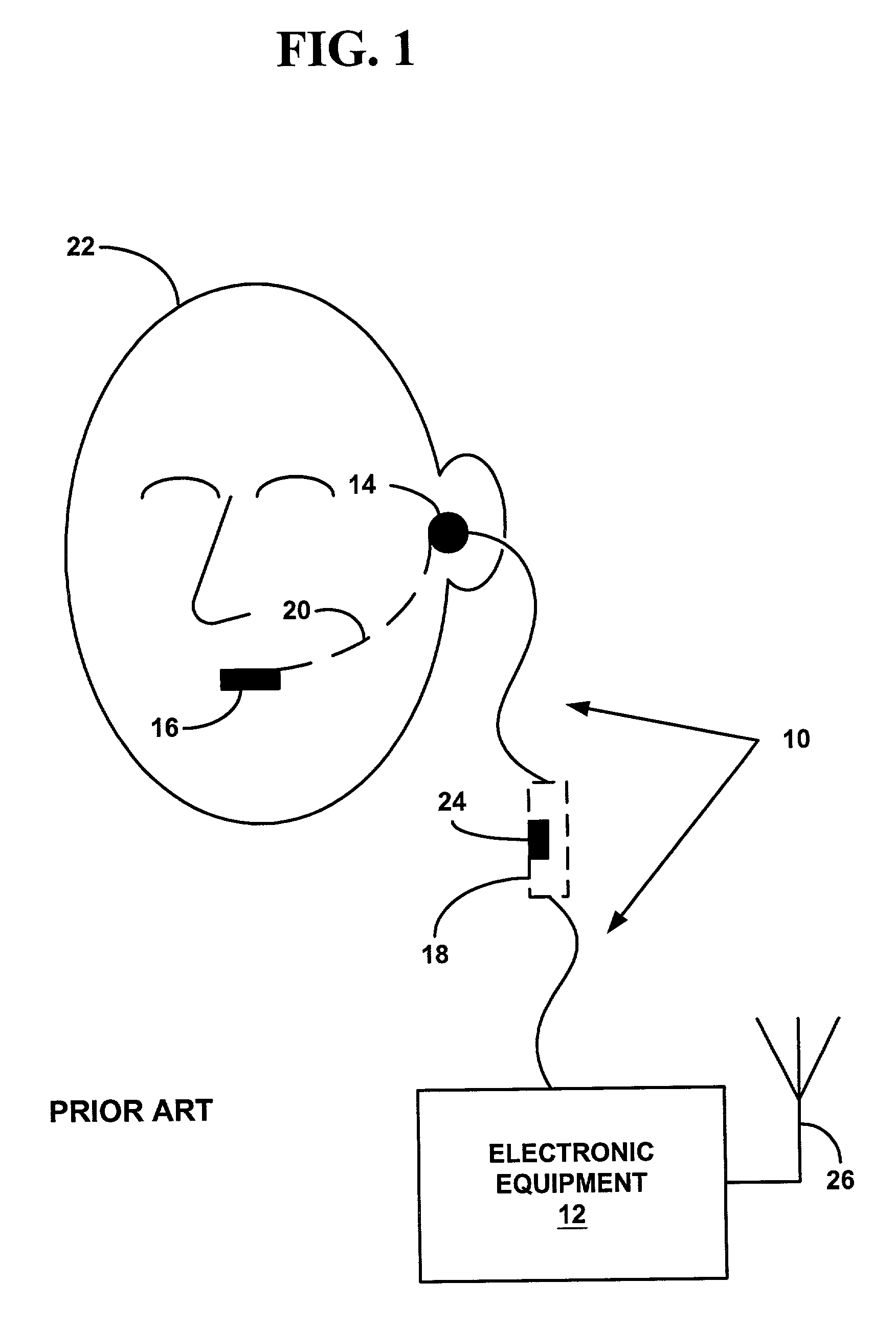
[0023]FIG. 1 is a block diagram illustrating components of an electrical coupling 10 between electronic equipment 12 and a headset 14 and / or microphone 16, 18. In an integrated configuration, the microphone 16 may suspend from the headset 14 by a boom 20. A user 22 places the headset on his head, locating the headset 14 proximate to or within his ear, and locating the microphone 16 proximate to his mouth. Alternatively, a mounting 24 along the electrical coupling 10 may have an integrated microphone 18. The mounting 24 hangs from the headset 14 such that the integrated microphone 18 is level with the mouth of the user 22. It should be understood, however, that the configuration and relationship of the headset 14 and microphones 16, 18 of FIG. 1 are for illustrative purposes. Other configurations are possible, such as a hand-held microphone, a lapel microphone, or integrated earpieces in a flight helmet. In general, the microphone 16, 18 may be wearable on clothing or accessories s...


PUM


Abstract

Apparatus and methods for transferring audio between a headset and electronic equipment over an optical link. The apparatus includes an electro-optical interface for electrically connecting to the electronic equipment, an optical link, and an electro-optical headset. Audio from the electronic equipment modulates a light source in the electro-optical interface. A modulated light signal is transmitted through the optical link to the electro-optical headset where it is demodulated and reproduced as the original audio in the ear of a user wearing the headset. Also, another audio from the user's mouth produces another modulated light signal in the electro-optical headset. The other modulated light signal is transmitted through the optical link to the electro-optical interface where it is demodulated to provide the other audio to the electronic equipment. The non-electrical optical link may improve audible communications between the electronic equipment and the headset in radio-frequency noisy environments. Also, the non-electrical optical link may prevent coupling with an aerial of the electronic equipment and improve radio propagation.

Description

FIELD OF INVENTION[0001]The present invention relates to electronic equipment having an audio output and / or input. More specifically, it relates to a headset and / or microphone that are optically coupled to the electronic equipment.BACKGROUND OF THE INVENTION[0002]Many pieces of electronic equipment produce an audio output, receive an audio input, or both. For example, conventional or cellular telephones, walkie-talkies, compact disc players, home audio equipment, portable radio receivers, and micro-cassette recorders involve providing audible communications to a user, or involve accepting audible communications from the user. In order to reduce the effects of ambient audible noise interfering with the audible communications, or to increase the user's privacy, the user may connect an headset and / or microphone to the equipment. In this manner, the user may hear the audible communications through the headset and / or speak the audible communications into the microphone. The headset may i...

Claims


Application Information

Patent Timeline
IPC IPC(8): H04R1/10
CPCH04B1/385H04R1/10H04R2420/07H04R2201/107H04R3/00
Inventor DENAP, FRANK A.ROSCOE, TIMOTHYEVANS, ARVID
Owner SPRING SPECTRUM LP
Why Eureka
Try Eureka