
Image processing apparatus and method

a technology of image processing and image information, applied in the field of image processing apparatus and image processing method, can solve the problems of inability to express an image in gradations comparable, difficult to multiplex additional information in a visually indiscernible manner, and the image information circulated over the internet can be demultiplexed, so as to reduce the deterioration of image quality and increase the extraction accuracy of information.

Inactive Publication Date: 2006-07-04
CANON KK
View PDF21 Cites 31 Cited by
  • Summary
  • Abstract
  • Description
  • Claims
  • Application Information

AI Technical Summary

Benefits of technology

[0034]With the view of overcoming the above-mentioned problems in the art, it is an object of the present invention to provide an image processing apparatus and an image processing method, which can bury information while suppressing deterioration of image quality and increasing extraction accuracy of the information.

Problems solved by technology

However, the above-proposed technique has problems given below.
Image information circulated over the Internet can be demultiplexed even after being subjected to digital filtering for improvement of image quality, such as edge emphasis and smoothing, if the circulated information has a certain level of noise durability.
Even with such an ink jet printer, however, it is impossible to express an image in gradations comparable to those of a photograph unless the so-called pseudo gradation process is employed.
Because an amount by which information is changed through both the processes 1401, 1402 is very large, it is quite difficult to multiplex additional information in a visually indiscernible manner and to properly demultiplex the multiplexed additional information from the information printed out on paper.
It is however difficult to input a highly durable signal while maintaining satisfactory image quality.
Also, the necessity of a number of complicated processes means that a very long processing time is required to achieve the series of steps from multiplexing to separation of the additional information.
However, when error diffusion is performed in the pseudo gradation process in a later stage, the band of the additional information is buried in a texture band generated with the error diffusion because of characteristics of a high-pass filter specific to the error diffusion.
This possibly results in a risk that demultiplexing of the additional information may be failed.
Thus, assuming the pseudo gradation process to be executed, the conventional methods shown in FIGS. 14 and 15 are not suitable.
In the case using the systematic dithering method, however, it is difficult to print out an image with high quality comparable to a photographic unless a printer having high resolution and very excellent mechanical accuracy is employed.
Also, when the dither matrix is cyclically changed, the band of particular frequency generated by a regularly arrayed dither is disturbed and image quality is adversely affected.
Moreover, a possibility of false demultiplexing is very high when the demultiplexing (separating) side employs a demultiplexing method that must estimate which dither matrix was used for binary-coding, in a state where a pixel value of image information as an original signal is uncertain.
In this proposed method, deterioration of image quality is unavoidable upon switching of the dither pattern as with the above-described former proposal.
Further, comparing with the former proposal, a larger quantity of additional information can be multiplexed, but color changes are caused with changes in array of color components and deterioration of image quality is increased particularly in a flat portion.
Additionally, it is thought that demultiplexing of on-paper information is more difficult to achieve.
Anyway, those proposed methods of changing the dither matrix has the problem in that deterioration of image quality is serious, while demultiplexing is comparatively difficult.
In the case of a print obtained by printing out information on paper, the texture cannot be sometimes satisfactorily reproduced because of deviations from the desired impact positions of ink droplets, e.g., dot twists.
However, determining a texture in an actual space area is easily affected by other color components, and a difficulty arises in separating the multiplexed information.
In that proposed method, however, processing conditions for each color component in the pseudo gradation process are not disclosed regarding specific correlation between colors.

Method used


Image

  • Image processing apparatus and method
  • Image processing apparatus and method
  • Image processing apparatus and method

Examples


first embodiment

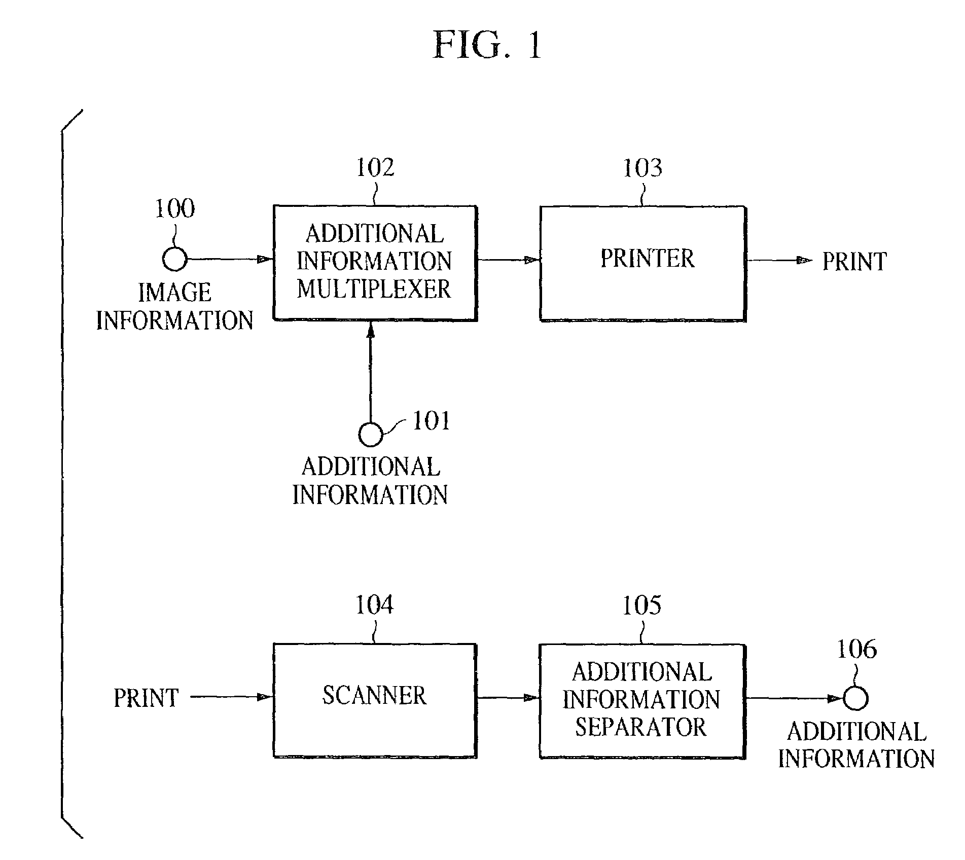
[0054]FIG. 1 is a block diagram showing a configuration of an image processing system according to a first embodiment of the present invention.

[0055]The system has input terminals 100 and 101. Image information of multi-gradations is input through the input terminal 100, and additional information to be buried in the image information is input through the input terminal 101. The additional information may be any of various items of information, e.g., voice information and text information that are independent of the image information input through the input terminal 100, and the copyright, the photographing date and place, the photographer, etc. regarding the image information input through the input terminal 100, as well as utterly different image information.

[0056]Also, the system has an additional information multiplexer 102 for burying additional information in the image information in a manner hard to discern visually. The additional information multiplexer 102 has the function...

second embodiment

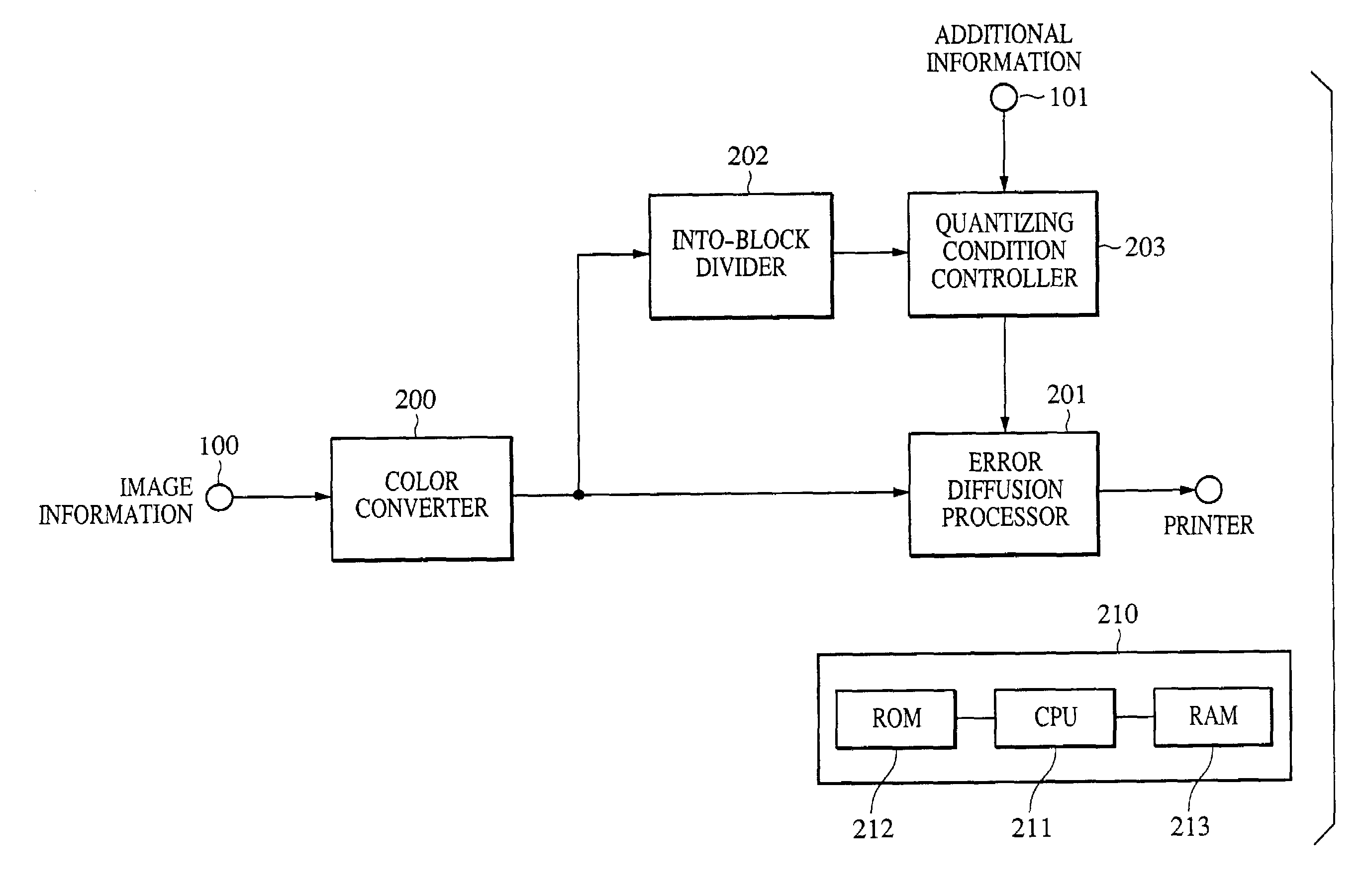
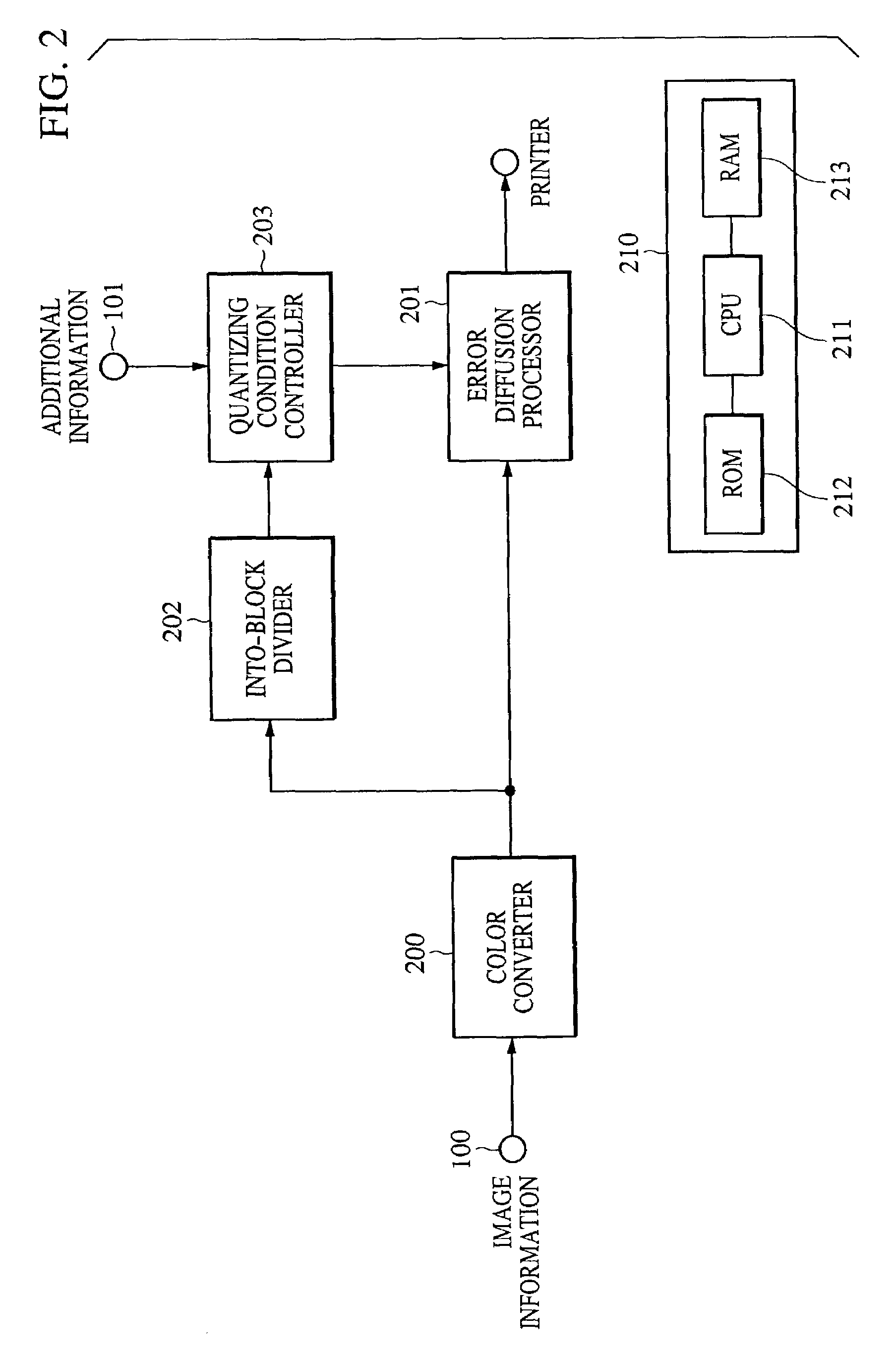
[0136]FIG. 11 is a block diagram showing a configuration of an additional information multiplexer according to a second embodiment of the present invention. The additional information multiplexer shown in FIG. 11 partly differs from that shown in FIG. 2. Therefore, the same components are denoted by the same numerals, and the following description is made of only the different points.

[0137]Referring to FIG. 11, an intra-block average density computing unit 1100 computes an average density of a particular color within a block of N×M pixels, which expresses one bit of additional information. Information of the computed average density is transmitted to a quantizing condition controller 1101 which controls a quantizing threshold in a similar manner to the first embodiment described above.

[0138]A process of deciding the quantizing condition A or the quantizing condition B in the quantizing condition controller 1101 is similar to that shown in FIG. 4, and hence a description of the proce...


PUM


Abstract

The invention provides a method of burying additional information in an image, which can suppress deterioration of image quality and reduce an extraction error rate when extracting the additional information. For implementing the method, in an image processing apparatus for burying predetermined information in a color image, the apparatus comprises an input unit for inputting a color image; a quantizing unit for quantizing the input color image with an error diffusion process for each of predetermined color components; and a quantizing condition control unit for controlling, in accordance with the predetermined information, periodicity at which an amplitude of a quantizing threshold is modulated by the quantizing unit. The quantizing condition control unit controls a phase in the amplitude modulation of the quantizing threshold to be different between at least one of the color components and the other color components.

Description

BACKGROUND OF THE INVENTION[0001]1. Field of the Invention[0002]The present invention relates to an image processing apparatus and an image processing method.[0003]2. Description of the Related Art[0004]Hitherto, researches have been extensively conducted on techniques for multiplexing, in information of an image, other information related to the image.[0005]Recently, the so-called watermarking technology has been standardized. With the watermarking technology, additional information, e.g., the author name and note on permission of use, is multiplexed in image information, such as photographs and paintings, in a manner hard to discern visually, and the multiplexed information is circulated over a network such as the Internet.[0006]As another application field, for the purpose of preventing fraudulent forging of paper money, stamps, stocks and bonds, etc., improved high quality of image output devices, such as printers, require a technique of burying additional information in an imag...

Claims


Application Information

Patent Timeline
IPC IPC(8): G06K9/38G06K9/00G06T1/00G06T5/00H04N1/387H04N1/405H04N1/52H04N1/60
CPCG06T1/005G06T1/0078G06T2201/0065G06T2201/0052
Inventor MIYAKE, NOBUTAKAUMEDA, KIYOSHIKUSAKABE, MINORU
Owner CANON KK
Learn More