
Calibration device for gas sensors

a gas sensor and calibration device technology, applied in the direction of gas analyser calibration, material electrochemical variables, instruments, etc., can solve the problems of loss of sensitivity, gas sensors such as pellistor sensors, biomimetic sensors, tin oxide sensors, etc., and achieve the effect of reducing the cost of gas sensors

Active Publication Date: 2006-07-11
HONEYWELL INT INC
View PDF10 Cites 25 Cited by
  • Summary
  • Abstract
  • Description
  • Claims
  • Application Information

AI Technical Summary

Benefits of technology

Enables continuous self-calibration of gas sensors, ensuring accurate detection of gas levels and preventing false alarms or missed toxic gas warnings by maintaining sensor sensitivity over time, even in hard-to-reach locations.

Problems solved by technology

However, a known problem with gas sensors is that they lose sensitivity over time.
Other types of gas sensors, such as pellistor sensors, biomimetic sensors, and tin oxide sensors that may be formed as thin film, thick film, sintered or MOSFET devices, may have similar problems.
However, if the instrument is in a difficult position to service, or if calibration of the gas sensor is not otherwise freely available, it is often impossible to confirm that the gas sensor is functioning correctly.
Therefore, as the gas sensor reaches the end of its working life, the output of the sensing cell may be insufficient to generate an alarm condition.
As a result, a situation could arise where toxic levels of gas are present, but the gas sensor is incapable of providing the requisite warning.
While such methods can uncover broken connections, they do not provide any information on the condition of the electrodes in terms of their ability to react with the gas to be detected.
Because of the difficulty in preparing gas / air mixtures at this dilution, because some toxic gases such as hydrogen sulphide and sulphur dioxide are readily absorbed by the materials used to make the calibration gas cylinder housings, and because the stability of these mixtures can be a problem, calibration gas cylinders have a limited shelf life.

Method used


Image

  • Calibration device for gas sensors
  • Calibration device for gas sensors

Examples


Embodiment Construction

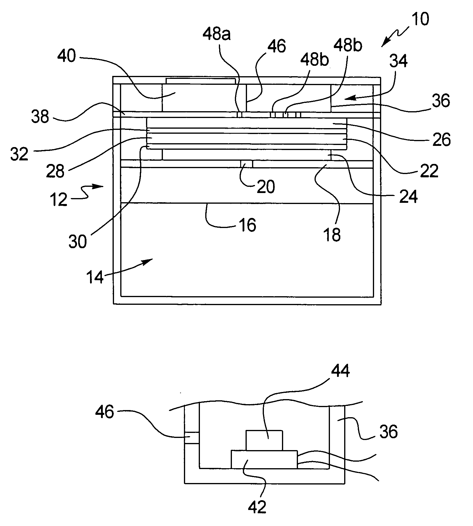
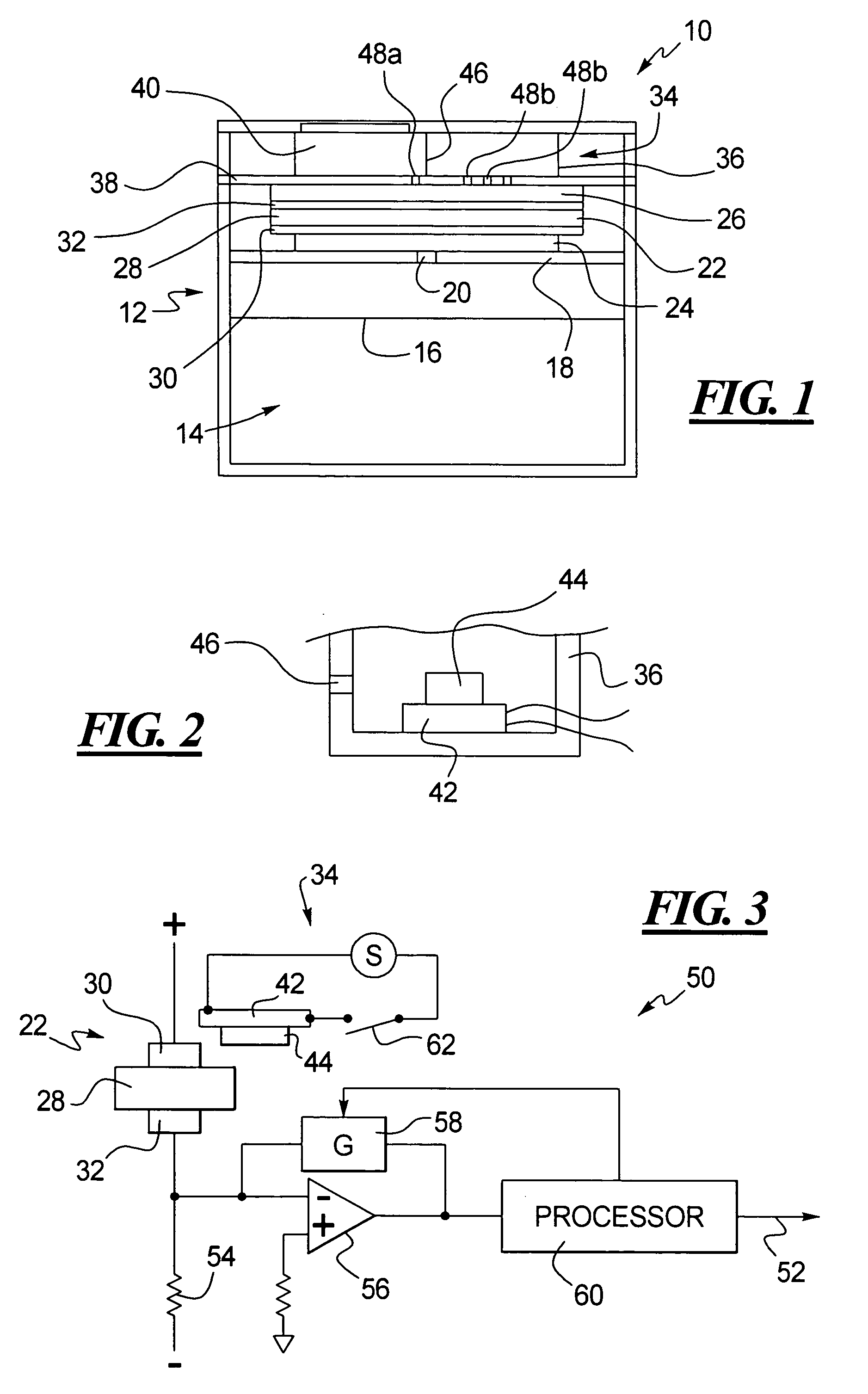
[0019]As shown in FIG. 1, a self-calibration gas sensor 10 has a housing that, for example, may be in the form of a can 12 that is covered at its open end by a cover 13. The can 12 and the cover 13, for example, may be made of nickel plated steel. The can 12 holds a substance 14 such as water or water gel or hydrophilic oxides like silica gel in an antiseptic solution. The substance 14 provides a source of water vapor for the self-calibration gas sensor 10. As shown in FIG. 1, the substance 14 has a level 16, although the can 12 can contain more or less of the substance 14. Other materials can be used for the substance 14 depending upon the particular application temperature range for the self-calibration gas sensor 10.

[0020]A support plate 18 is provided in the can 12 above the level 16 of the substance 14. The support plate 18 has a hole 20 therethrough to permit the flow of vapor from the substance 14 through the support plate 18. The support plate 18, for example, may be a stain...


PUM

PropertyMeasurementUnit
hydrophobicaaaaaaaaaa
concentrationaaaaaaaaaa
conductiveaaaaaaaaaa

Abstract

A gas sensor includes a gas detector, a reference gas generator, and a circuit. The reference gas generator includes a heater and a gas releasing material. The gas releasing material is in proximity to the heater such that, when the heater is energized during calibration, the gas releasing material releases an overpressure of a reference gas to the gas detector and such that, when the heater is not energized, the gas releasing material releases no substantial overpressure of the reference gas to the gas detector. The circuit energizes the heater during calibration and is responsive to an output of the gas detector during the period when the gas detector is provided the reference gas so as to calibrate the gas sensor.

Description

TECHNICAL FIELD OF THE INVENTION[0001]The present invention relates to the internal generation of a reference gas that is used to calibrate a gas sensor.BACKGROUND OF THE INVENTION[0002]Gas sensors have been in use for some time to sense various gases such as hydrogen, oxygen, carbon monoxide, etc. One form of a gas sensor is an electrochemical cell that uses a catalytic electrode so that the gas to be detected is either oxidized or reduced with the exchange of electrons. The flow of current due to the oxidation or reduction of the gas is then detected as a measure of the concentration of the gas to be detected.[0003]However, a known problem with gas sensors is that they lose sensitivity over time. For example, the working life of an electrochemical cell is determined by the activity of the cell's catalytic electrode that is used to detect gas within the sensor. This activity is gradually reduced over time by contaminant gases and poisons such that the sensitivity of the sensor drif...

Claims


Application Information

Patent Timeline
Patent Type & Authority Patents(United States)
IPC IPC(8): G01N27/28G01N27/416G01N33/00
CPCG01N33/0006
Inventor WOOD, ROLAND A.LIU, JAMES
Owner HONEYWELL INT INC
Learn More