Method and system for generating an x-ray exposure

a technology of exposure and x-ray, applied in the field of generating an exposure, can solve the problems of disadvantageous creation of shadow formation, achieve the effects of reducing distortion artifacts, facilitating image series production, and improving projection geometry

Inactive Publication Date: 2006-07-11
SIEMENS AG
View PDF4 Cites 30 Cited by
  • Summary
  • Abstract
  • Description
  • Claims
  • Application Information

AI Technical Summary

Benefits of technology

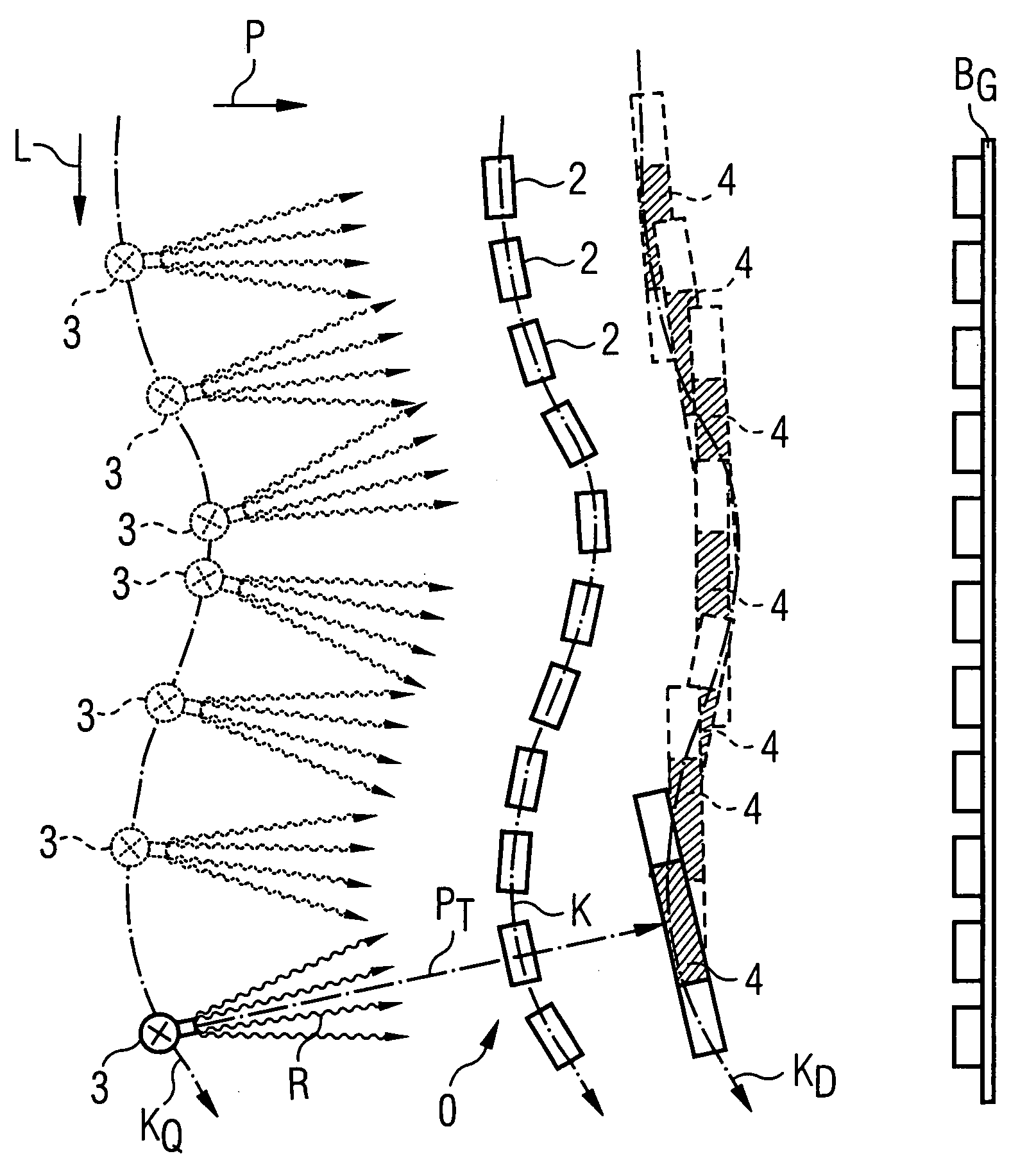
[0010]Thus, to generate the partial exposures, the x-ray source and the x-ray detector are not simply shifted parallel to one another linearly along the longitudinal direction of the exposure subject, and consequently not only simple partial projections of the individual sections are produced in the main projection direction standing perpendicular to the longitudinal direction of the exposure subject. The overlappings and parallax effects due in particular to the curved geometry, and the shadow formations caused thereby, can be reduced or even completely prevented. The quality of the overall exposure thus can be significantly improved in a simple manner. Given use of such a method to acquire a spinal column, the structures at the vertebrae ends and between the individual vertebrae are also well represented in detail.
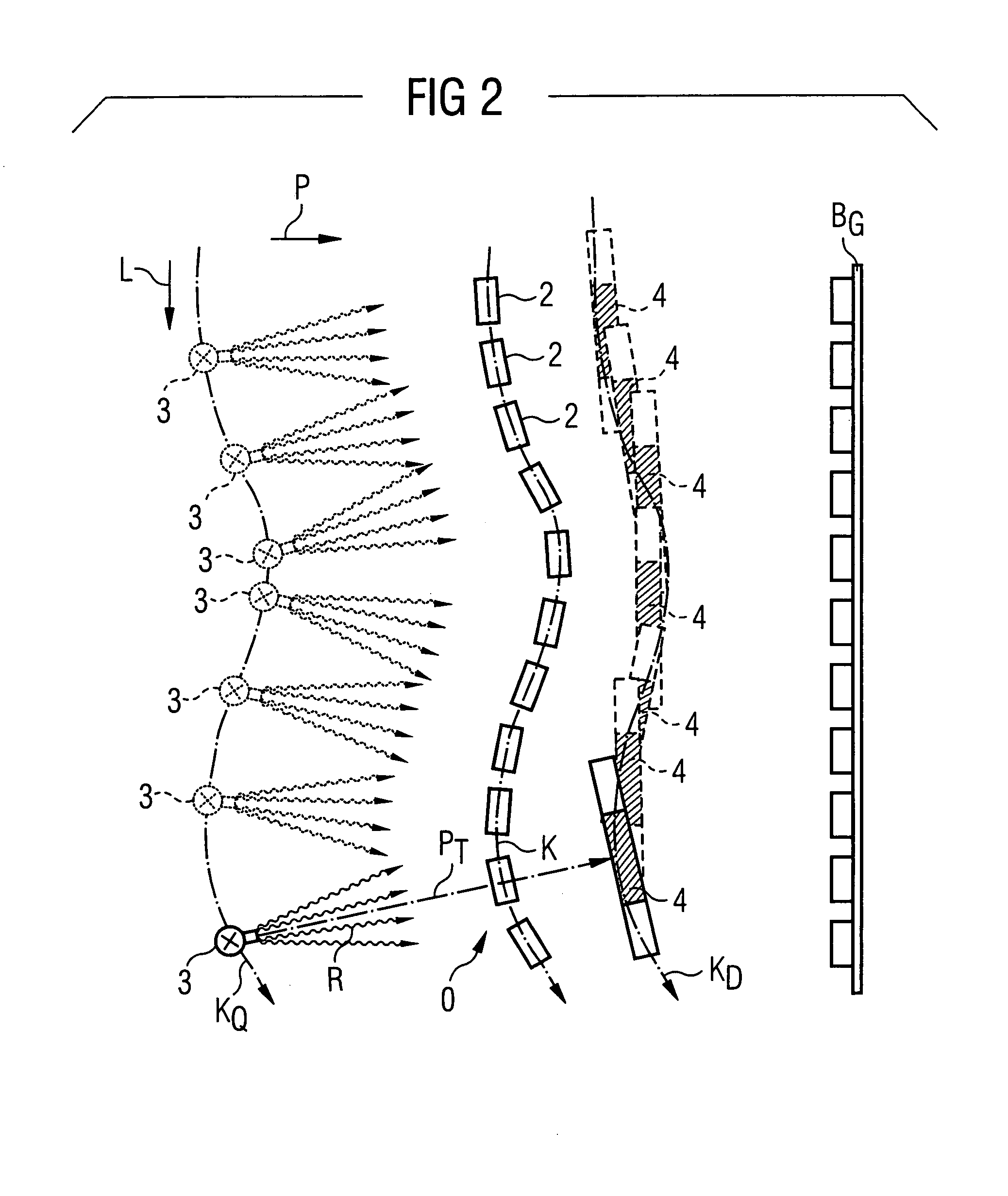
[0011]To adapt to the curve of the exposure subject, the x-ray source and the x-ray detector preferably are each positioned and aligned relative to one another and to the section to be acquired of the exposure subject, such that the current projection direction given the appertaining partial exposure (also called “partial exposure projection direction” in the following) lies essentially at a right angle to the section to be acquired of the exposure subject, meaning that the partial exposure projection direction is at a right angle to the local extension direction of the appertaining section or, respectively, given significantly curved sections, for example, at a right angle to a median (middle or average) tangent or the like, Undesired superimposition and parallax effects in the respective partial exposure due to a non-alignment of the exposure subject section with regard to the projection direction are almost completely prevented. In the acquisition of a spinal column image, it is thus ensured that, even in the curved regions of the spinal column, adjacent vertebrae ends do not overlap in the current partial exposure projection, and thus the details of the vertebrae ends and the intervertabral disk structures lying between them are acquired with much more detail being visible than was conventionally possible.
[0013]Moreover, one or both of the x-ray source and the x-ray detector is / are positioned on a curve essentially following the geometry of the exposure subject. The source is positioned on a curve preceding (with respect to radiation propagation) the subject, and the detector is disposed on a curve after the subject. This means the x-ray source and / or the x-ray detector are not moved, is conventional, as along a straight line parallel to the longitudinal direction of the exposure subject, but rather are moved along a curve that is adapted to the geometry of the exposure subject. For the acquisition of a spinal column image series, the positioning of the x-ray source and / or of the x-ray detector ensues, for example, along a double-s curve. This allows, in each partial exposure, independent of the current partial exposure projection direction, the x-ray source and the x-ray detector to have approximately the same separation from one another and from the currently exposed section of the exposure subject.
[0015]In a preferred exemplary embodiment to generate the exposure series, an x-ray detector is used which has a relatively narrow active detector surface in the longitudinal direction of the exposure subject. With such a narrow detector surface a larger number of partial exposures must be produced in order to generate an overall x-ray exposure, but the advantage of a higher number of partial exposures is that a significantly better adaptation of the projection geometry of the exposure series to the geometry of the exposure subject is possible, and distortion artifacts can be minimized. By the use of a detector that is narrow in the longitudinal direction of the exposure subject, it is ensured that, given the increased number of partial exposures, the overlap between the individual adjacent partial exposures is only as large as is necessary for a later merging of the individual partial exposures, and unnecessary regions are not doubly acquired. Achieving this with the conventional use of digital detectors would be associated with significant loss of time for the readout of the unnecessary detector regions. The shortened readout process achieved with the inventive method and system enables a faster image series production and therefore provides for a reduction of the movement artifacts and distortion artifacts.
[0016]In an alternative preferred exemplary embodiment, only one narrow region of a detector surface of an x-ray detector in the longitudinal direction of the exposure subject is used as the active surface, This has the advantage that a “normal” digital x-ray detector with the typical dimensions can be used. The inventive x-ray system thus also can be used without retrofitting for different applications. For use of the system for implementing the inventive method, it is provided with a suitable detector control so that only a smaller detector surface is activated or read out, so the same timesavings per exposure is achieved as is the case with use of a narrower detector. The middle region of the detector surface is preferably used as he active surface.

Problems solved by technology

This is particularly a problem given complicated skeletal structures such as the spinal column.
With the known type of generation of the individual partial exposures by means of an x-ray source moving in a straight line and an x-ray detector running in parallel, shadow formations are disadvantageously created directly in the edge regions and the intervening spaces between the vertebrae due to overlapping of adjoining vertebrae and due to parallax effects.
This can lead to defects that are not clearly associated with a specific vertebra.
A similar problem is represented by exposures of other large skeletal structures, in particular in the joint areas.

Method used


Image

  • Method and system for generating an x-ray exposure
  • Method and system for generating an x-ray exposure
  • Method and system for generating an x-ray exposure

Examples


Embodiment Construction

[0030]In the figures and the further explanations, it is assumed that an optimally shadow-free representation of the spinal column of a person is generated by means of the inventive method. As previously explained, however, the invention is not limited to such an application.

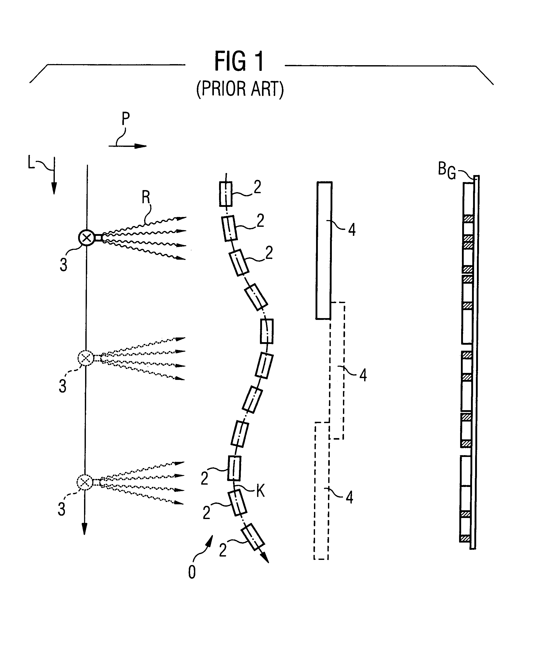
[0031]FIG. 1 schematically shows as an exposure subject, the individual vertebras 2 of a spinal column O in a typical “double-s shape”. This spinal column O essentially extends in a longitudinal direction L.

[0032]Conventionally, a complete exposure of such a spinal column O is generated by an x-ray source 3 and an x-ray detector 4 being moved in tandem in front of and behind the spinal column O on straight lines parallel to the longitudinal direction L. At specific positions—here at three positions—partial exposures of adjacent sections of the spinal column O are generated. These partial exposures are then combined into an overall x-ray exposure BG. A problem with this acquisition method is that, due to the typi...


PUM

PropertyMeasurementUnit
angleaaaaaaaaaa
lengthaaaaaaaaaa
dimensionsaaaaaaaaaa

Abstract

In a method and system for generating an x-ray exposure of an examination subject extending in a longitudinal direction and exhibiting, in a main projection direction, a geometry that is curved at least in sections, an x-ray source and an x-ray detector are respectively positioned and aligned appropriately with regard to one another and to the section to be acquired of the exposure subject in order to generate partial exposures along a curved course substantially adapted to the geometry of the exposure subject. The partial exposures of the sections subsequently are combined into an overall x-ray exposure of the exposure subject.

Description

BACKGROUND OF THE INVENTION[0001]1. Field of the Invention[0002]The present invention concerns a method and system for generating an x-ray exposure of an examination subject exhibiting a curved geometry.[0003]2. Description of the Prior Art[0004]Methods are known for generating an x-ray exposure of an exposure subject extending in a longitudinal direction which, at least in sections, exhibits a curved geometry in a main projection direction transverse to the longitudinal direction, wherein initially partial exposures of individual sections of the exposure subject are generated by positioning of an x-ray source and an x-ray detector at various positions along the longitudinal direction of the exposure subject, and then the partial exposures of the sections are combined into an overall x-ray exposure of the exposure subject. Moreover, x-ray systems are known for generating an x-ray exposure of such an exposure subject; which have an x-ray source and an x-ray detector that can each be ...

Claims


Application Information

Patent Timeline
Patent Type & Authority Patents(United States)
IPC IPC(8): H05G1/02A61B6/00G01N23/04
CPCA61B6/4441A61B6/4464A61B6/4476A61B6/488A61B6/505G01N23/04
Inventor SPAHN, MARTIN
Owner SIEMENS AG
Why Eureka
Try Eureka