
Control apparatus for hybrid vehicle

a control apparatus and hybrid technology, applied in the direction of motor/generator/converter stopper, dynamo-electric converter control, jet propulsion mounting, etc., can solve the problems of deteriorating fuel consumption efficiency and difficulty in performing the desired assisting operation of the motor, so as to reduce the fuel consumption of the internal combustion engine and keep the fuel consumption efficiency from deteriorating

Active Publication Date: 2006-07-11
HONDA MOTOR CO LTD
View PDF8 Cites 24 Cited by
  • Summary
  • Abstract
  • Description
  • Claims
  • Application Information

AI Technical Summary

Benefits of technology

The present invention provides a control apparatus for a hybrid vehicle that improves fuel efficiency by optimizing the use of energy in the vehicle's power storage unit. The control apparatus includes an upper limit motor torque calculating device that sets an upper limit value of motor torque based on the vehicle's power storage unit, a regeneration / assistance amount integrated value calculating device that calculates a residual amount of energy generated by the motor during vehicle deceleration, and a correction coefficient setting device that sets a correction coefficient to correct for a decrease in the upper limit value of motor torque. Additionally, a motor assistance region decreasing device restricts the motor torque to below the correction upper limit value. These features allow for optimal fuel consumption and improved fuel efficiency during various driving situations.

Problems solved by technology

Consequently, for example at the time of acceleration of the vehicle, it becomes difficult to perform the desired assisting operation by the motor.
Furthermore, in the case where there is a likelihood of the power storage unit reaching an over discharging state, it is necessary to operate the motor as a generator by the output from the internal-combustion engine so as to charge the power storage unit, resulting in a problem that the fuel consumption efficiency is deteriorated, if the execution frequency of this power generation is increased.

Method used


Image

  • Control apparatus for hybrid vehicle
  • Control apparatus for hybrid vehicle
  • Control apparatus for hybrid vehicle

Examples


Embodiment Construction

[0022]Hereunder is a description of a control apparatus for a hybrid vehicle according to an embodiment of the present invention with reference to the appended drawings.

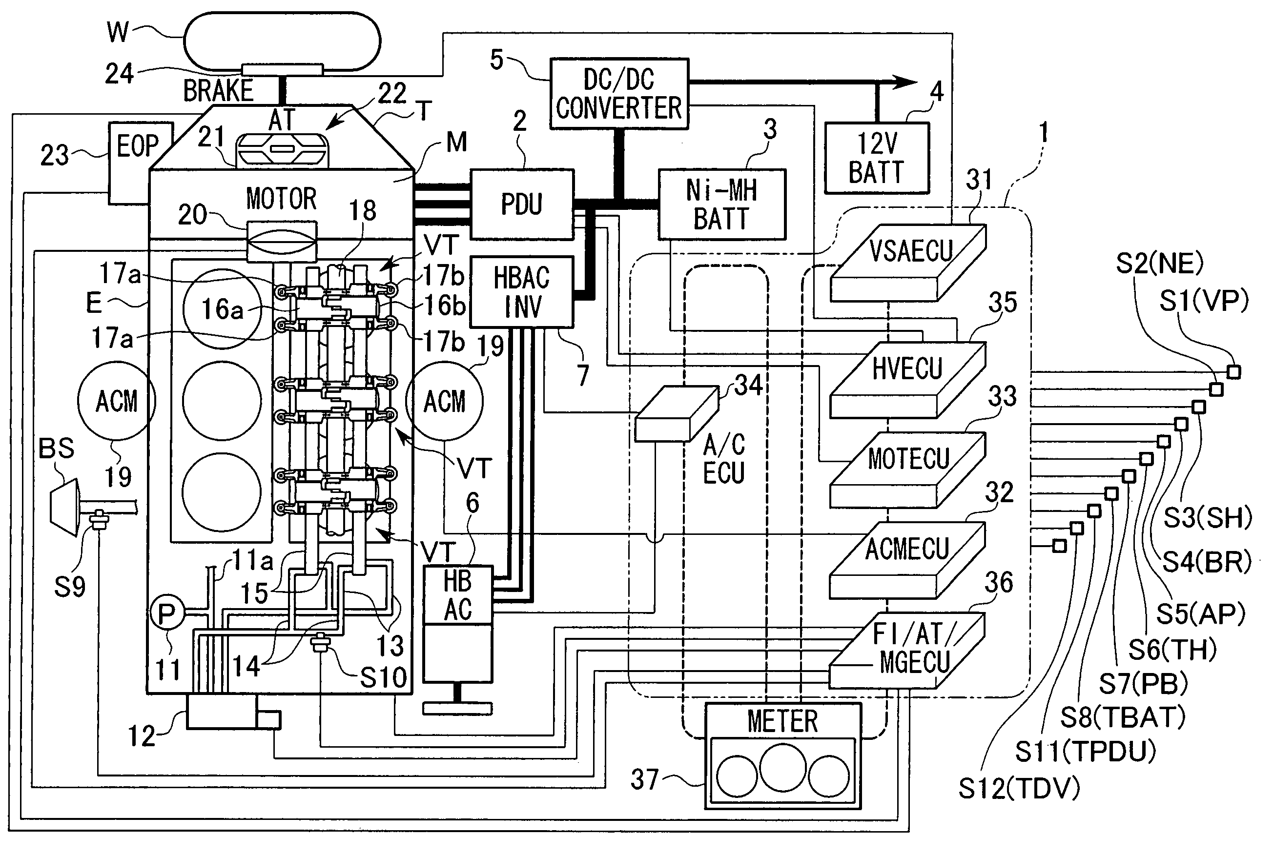
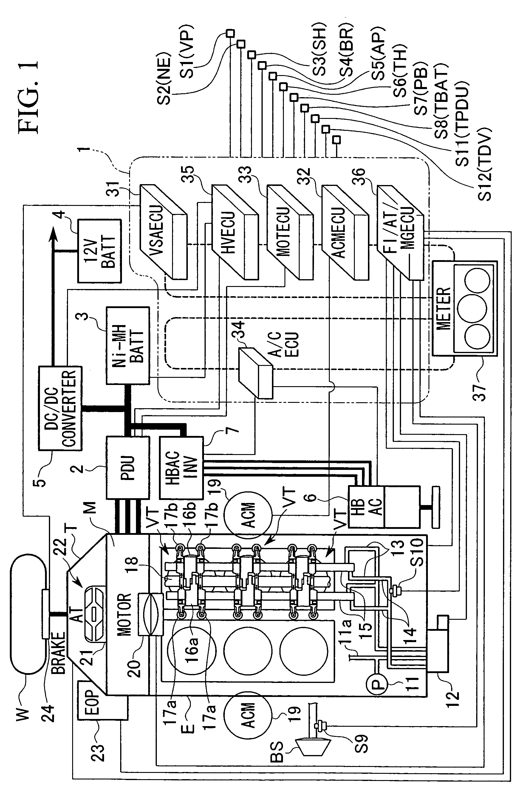
[0023]FIG. 1 shows a parallel hybrid vehicle according to the embodiment of this invention having a construction where an internal-combustion engine E, a motor M, and a transmission T are connected directly in series. The driving force of both the internal-combustion engine E and the motor M is transmitted, for example, from the transmission T such as an automatic transmission (AT) or manual transmission (MT),) to the driving wheels W of the vehicle, via a differential gear (not shown) which distributes the driving force between driving wheels W on the right and the left (front wheels or rear wheels. Moreover, when a driving force is transmitted from the driving wheel W side to the motor M side at the time of deceleration of the hybrid vehicle, the motor M functions as a generator to generate so-called regenerative b...


PUM


Abstract

A motor charge-discharge torque limit correction coefficient for during cylinder deactivation enlargement assistance, which changes with an increasing trend according to an increase in a regeneration / assistance integrated residual amount which is an integrated value of the energy amount obtained during deceleration regeneration of vehicle, that is a correction coefficient which corrects to decrease an energy management discharge torque limit which is an upper limit value of motor torque set according to for example, an energy state in high voltage electrical equipment and an operating state of the vehicle, when assisting the output from the internal-combustion engine by the motor, is calculated. A value obtained by correcting the energy management discharge torque limit is set to an energy management discharge torque limit for cylinder deactivation enlargement assistance, and a cylinder deactivation upper limit ENG torque is added so as to calculate a cylinder deactivation upper limit torque.

Description

BACKGROUND OF THE INVENTION[0001]1. Field of the Invention[0002]The present invention relates to a control apparatus for a hybrid vehicle which is mounted in a hybrid vehicle propulsion driven by jointly using an internal-combustion engine and a motor, and wherein the driving force from at least one of the internal-combustion engine and the motor is transmitted to the driving wheels.[0003]This application is based on Japanese Patent Application No. 2003-192306, the contents of which are incorporated herein by reference.[0004]2. Description of Related Art[0005]Conventionally, for example, in a hybrid vehicle which comprises an internal-combustion engine and a motor as a power source and wherein the driving force from at least one of the internal-combustion engine and the motor is transmitted to the driving wheels for propulsion, a control apparatus for a hybrid vehicle has been well known which calculates the throttle opening for minimizing the fuel consumption of the internal-combus...

Claims


Application Information

Patent Timeline
Patent Type & Authority Patents(United States)
IPC IPC(8): H02P7/00B60K6/485B60W20/00B60K6/54B60L15/00B60L50/16B60W10/06B60W10/08B60W10/18B60W10/26
CPCB60K6/485B60K6/543B60W10/06B60W10/26Y10T477/30B60W20/00Y02T10/6226Y10T477/20Y02T10/62B60W20/13B60W20/11
Inventor WAKASHIRO, TERUOASAKAWA, MASANOBUHANADA, KOHEINIKI, MANABUHACHIRO, TOSHITAKANISHI, TOMOHIRO
Owner HONDA MOTOR CO LTD
Learn More