Device and method for carrying out experiments in parallel

a technology of parallel operation and device, which is applied in the field of parallel device and method, can solve the problems of inability to achieve temperature above 350° c. for individual vessels operated in parallel, the requirements of carrying out experiments can be substantially more complex, and the temperature of the test tube is not provided individually, so as to achieve the effect of reducing the number of connection points, ensuring the safety of operation, and improving the overview

Inactive Publication Date: 2006-07-11
BAYER AG
View PDF12 Cites 79 Cited by
  • Summary
  • Abstract
  • Description
  • Claims
  • Application Information

AI Technical Summary

Benefits of technology

[0115]The particular substance distributors make it possible to distribute substance and energy flows to all the reactors in a very small space. The special sheet-type structure of the module and the use of very compact valves, which are suitable for extreme conditions, drastically reduce the number of connection points, and therefore possible leakage points at high pressures, as well as the length of the necessary capillary lines, which leads to a better overview, higher operational safety and therefore to simple and safe handling of the device according to the invention. The special design of the controllable valves that are preferably used, with e.g. an integrated pneumatic drive in the region of the valve head plate, considerably reduces the response or switching times of the valves. Furthermore, for automated uniform test runs of parallel reaction systems, it is necessary to have very many controllable valves which need to be fitted in the smallest of spaces. It is not uncommon to require up to 10 valves per reactor, so that the tailored valve design is substantially more economical and cost-effective than conventional solutions with known valve types.
[0116]A further advantage is provided by the supply unit. The additionally required miniaturized reactor equipment peripherals are concentrated on the supply unit, so that a test can be carried out fully automatically. These include various additional miniaturized equipment items, e.g. storage containers, buffers, filtration units, mixer-settlers, on-line analysis, pumps and further valves and the necessary sensors and actuators for measuring physical parameters. The supply unit may also be a component of a liquid handler, and may optionally be positioned in a glove-box. This makes it possible to handle liquids and solids under inert conditions. It is thereby possible to combine the sample preparation directly with the carrying out of parallel tests.
[0117]The monitoring unit, e.g. consisting of a sensor and actuator circuit board, can be positioned directly on the supply unit, so as to permit short electrical cable paths. Because of the multiplicity of different sensors and actuators, up to 500 so-called MSR points can be interconnected and routed in bundles via multi-stranded ribbon cables to the process control system. This module technology saves on space and costs, and produces flexibility in the use of different sensors for various tasks when carrying out parallel tests. In particular in the case of varying tasks, it is easy to carry out upgrading or refitting.

Problems solved by technology

For the latter applications, the technical requirements when carrying out experiments can be substantially more complex than in the case of HTS for active-agent research (e.g. owing to fluctuating process parameters: temperature, pressure, stirring etc.).
Individual recording of the temperatures in the test tubes is not provided for in the majority of cases, however.
Temperatures above 350° C. cannot yet be achieved for individual vessels operated in parallel.
These temperature and pressure ranges place great demands on the technique of the overall system, so that known reactor systems and system components, such as manual valves, controllable fitments, pipeline screw connections, reactors and temperature adjustment systems cannot generally be used.
Even very minor leaks in the overall equipment, e.g. in valves or commercially available cutting-ring or clamping-ring screw connections, render all the results unusable.
If these connection points are multiplied by the degree of parallel operation, there are easily several hundred potential leak points in a very small space, which need to be checked for leaks and make it impossible for the operator to work efficiently with the miniaturized parallel reactor system.

Method used


Image

  • Device and method for carrying out experiments in parallel
  • Device and method for carrying out experiments in parallel
  • Device and method for carrying out experiments in parallel

Examples


examples

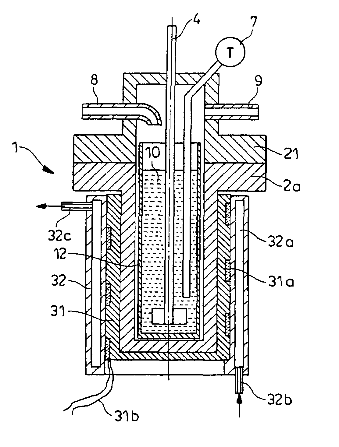
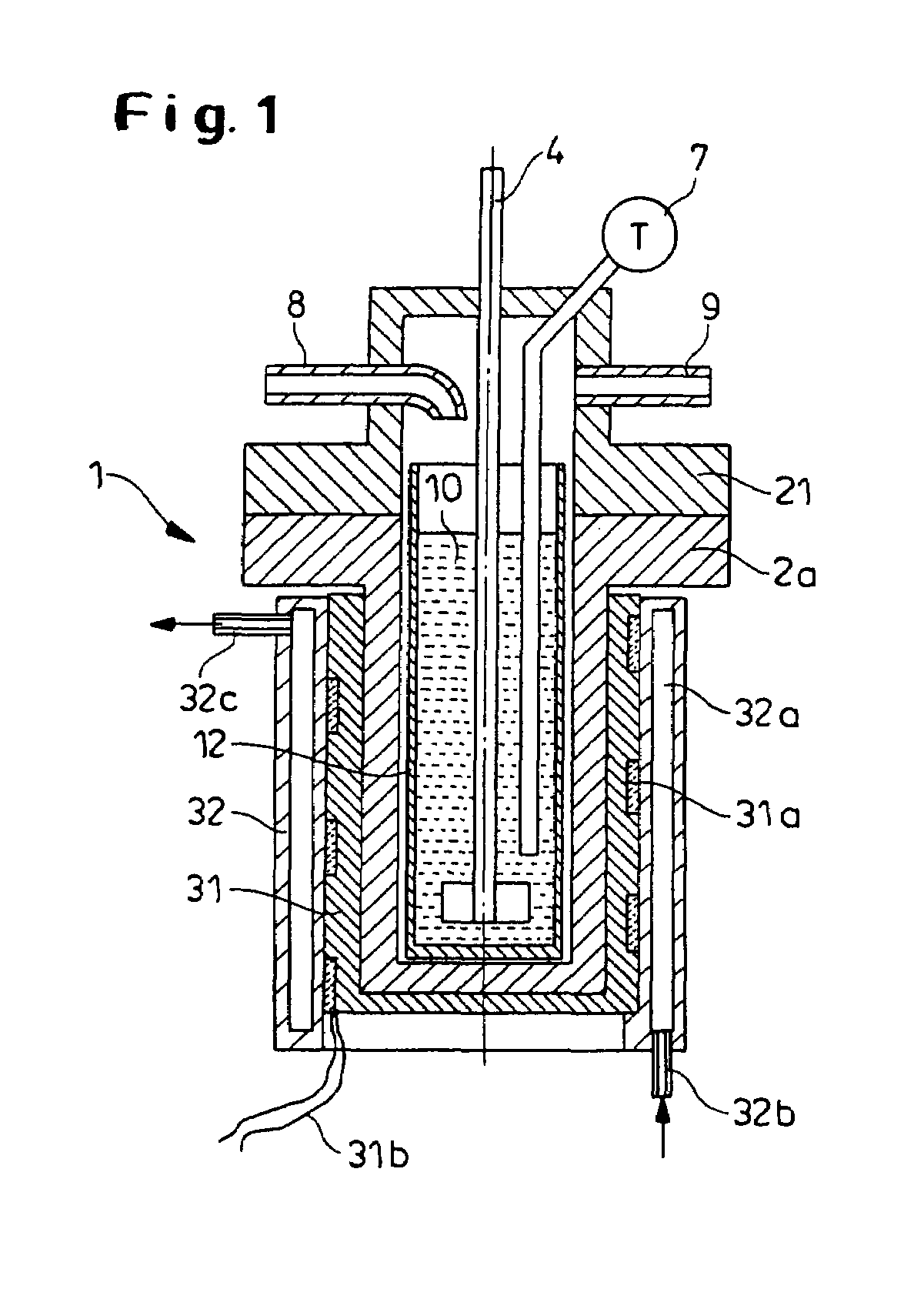
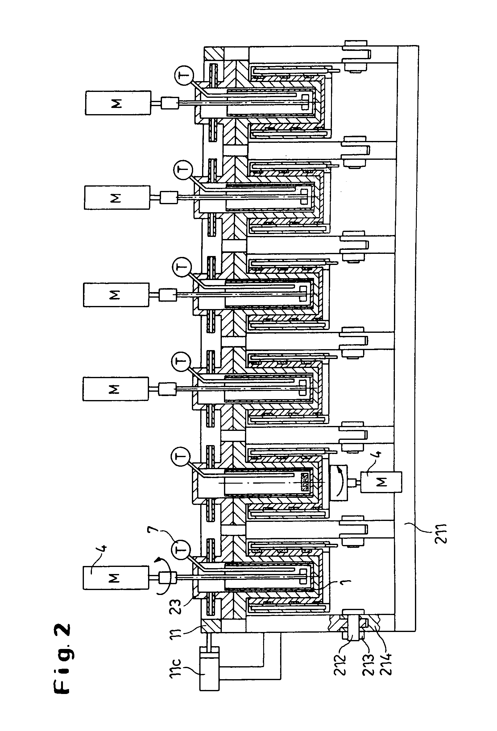
[0147]FIG. 7 illustrates an overview of the various parts of a test device and their interconnection, e.g. the modularly constructed individual reactor 1 with a lid module 22, the substance distributors 702, 702a with the plate valves 704 and the supply unit 701, which is embodied here as a simple assembly plate. In special applications, the supply unit 701 is designed with integrated main distribution channels as a flat substance distributor 80 (see FIG. 8) and is allocated to at least one individual reactor. Interface modules 714, 724 are furthermore provided in the form of a sensor and actuator circuit board, which is in turn attached to the monitoring unit 700 and a PC (not shown).

[0148]It can be seen from FIG. 7 that the individual reactor 1 contains a sample vessel (12 in FIG. 1) and a magnetic stirrer 4 is used, which is driven by a magnetic coupling with a motor (M). The modular structure of the individual reactor 1 is further described below with another stirrer device 4 in...


PUM

PropertyMeasurementUnit
temperatureaaaaaaaaaa
pressureaaaaaaaaaa
temperaturesaaaaaaaaaa

Abstract

Modular device and method for carrying out experiments in parallel on process substances to develop technical methods, comprising at least a multiplicity of individual reactors which are controllable independently of one another said reactors being comprised of pressure-tight chambers having separable sample vessels, and optionally, stirring devices, heating instruments, cooling instruments, or both, a monitoring unit for monitoring or controlling at least the pressure and the temperature in the individual reactors, pressure-tight lids having independent feed lines and optionally independent discharge lines for individual process substances; a plurality of the lids being simultaneously sealable upon the rectors by a common sealing means (11).

Description

[0001]The present invention relates to a method and to a device for efficiently carrying out experiments under realistic conditions to develop methods, in particular chemical and physical methods. The device for carrying out the experiments, which are miniaturized and organized in parallel for this purpose, comprises individual containers in which experiments are carried out, as well as apparatus for the distribution and feed of the required substances into the individual containers; sensors, actuators, and apparatus for process control and analysis. The method comprises reliable, automatic conduct of the experiments, including initialization, setting all the reaction parameters, dosing the substances, taking samples and reproducing the initial state, as well as transfer of the data recorded during the experiments to a database.BACKGROUND OF THE INVENTION[0002]The efficiency of many experimentally based developments can be increased by miniaturization, automation and parallel operat...

Claims


Application Information

Patent Timeline
Patent Type & Authority Patents(United States)
IPC IPC(8): G01N21/00B01J19/00G01N35/00B01L3/00B01L7/00C40B30/08C40B40/14C40B40/18C40B60/14G01N37/00
CPCB01J19/0046B01L3/50851B01L7/00Y10T436/11B01J2219/00389B01J2219/00418B01J2219/00477B01J2219/00481B01J2219/00495B01J2219/00585B01J2219/0059B01J2219/00601B01J2219/00698B01J2219/0072B01J2219/00722B01J2219/00745B01J2219/00747B01L2200/14B01L2300/04B01L2300/14C40B30/08C40B40/14C40B40/18C40B60/14B01J2219/00283
Inventor JAHN, PETERWIESSMEIER, GEORGKRUMBACH, BERNHARDROSE, REINHOLDSIEBERT, THOMASKRAUTKRAMER, RAINER
Owner BAYER AG
Why Eureka
Try Eureka