Alarm with remote monitor and delay timer

a technology of delay timer and monitor, which is applied in the field of alarms, can solve the problems of accidental or high-cost placement of alarms, misuse of alarms, and compromising the privacy of individuals, and achieves the effects of convenient installation and maintenance, reliable, and flexibl

Inactive Publication Date: 2006-07-11
MARSHALL CRANBROOK
View PDF20 Cites 195 Cited by
  • Summary
  • Abstract
  • Description
  • Claims
  • Application Information

AI Technical Summary

Benefits of technology

[0023]It is a further object of the present invention to provide an alarm apparatus that is reliable, flexible, and easy to install and maintain.
[0024]It is a further object of the present invention to provide an alarm apparatus that protects the privacy of the public.
[0029]When the fiber is installed at an angle it will detect a major portion of light in the direction of the hole and not perpendicular to the surface. This is unexpected and will allow the detection of light to be very specific in coverage without interfering with the operation of the equipment protected.
[0032]Light monitoring with the fiber optics and the light sensor techniques does not infringe upon security or privacy. The present invention will protect the equipment and persons from illegal or immoral wireless and digital monitoring.
[0036]Radio detection with the remote antenna and delay timer technique does not infringe upon security or privacy. The present invention will protect the equipment and persons from illegal (or immoral) wireless and digital monitoring.

Problems solved by technology

The privacy of the individual is being compromised by new wireless video cameras.
They are being used illegally or improperly in or around private places such as changing rooms, bathrooms, motel rooms, and in public places like ATM machines and showers.
Locating these have been accidental or at great cost.
These “bugs” are a threat to the privacy of the individual and businesses.
Leaky data cables may also be located as they are a security and reliability problem in communications.
This method of detection is very expensive and provides for neither continued security nor guaranteed future privacy.
These commercial alarm systems normally do not defend against a specific device being installed such as a radio transmitter (“wireless bug”).
They do not protect critical devices (such as a smoke detector, emergency switch or card reader) from being modified, covered, or compromised.
The ATM may be shut down from lighting problems, which alerts the criminal to protection and causes any illegal activity to move to less protected equipment.
However, with newer technology the criminal can wait in the car and collect all the information needed, email the information across the country and the customer does not even realize the bank account has been compromised.
This is done with an unauthorized card swipe (fraud) device and a video camera illegally installed at the ATM machine.
Preventing this criminal technique is known as “anti-skimming”, however it will not detect the unauthorized card reader or wireless camera located a short distance away.
This will only work for the newer ATM machines with good communications, but will not support older ATM machines.
These are very complex methods to protect the ATM machine and require factory installation, alignment, and new computer programming.
The suggested methods would be difficult to incorporate in the older machines.
Any monitor at the card reader slot will not detect the unauthorized wireless camera or recording device that has been placed at a location away from the card reader.
There are many new styles of machines being produced daily that look different from the older machines and could “look fishy”.
This suggestion could be confusing to the average ATM user.

Method used


Image

  • Alarm with remote monitor and delay timer
  • Alarm with remote monitor and delay timer
  • Alarm with remote monitor and delay timer

Examples


Embodiment Construction

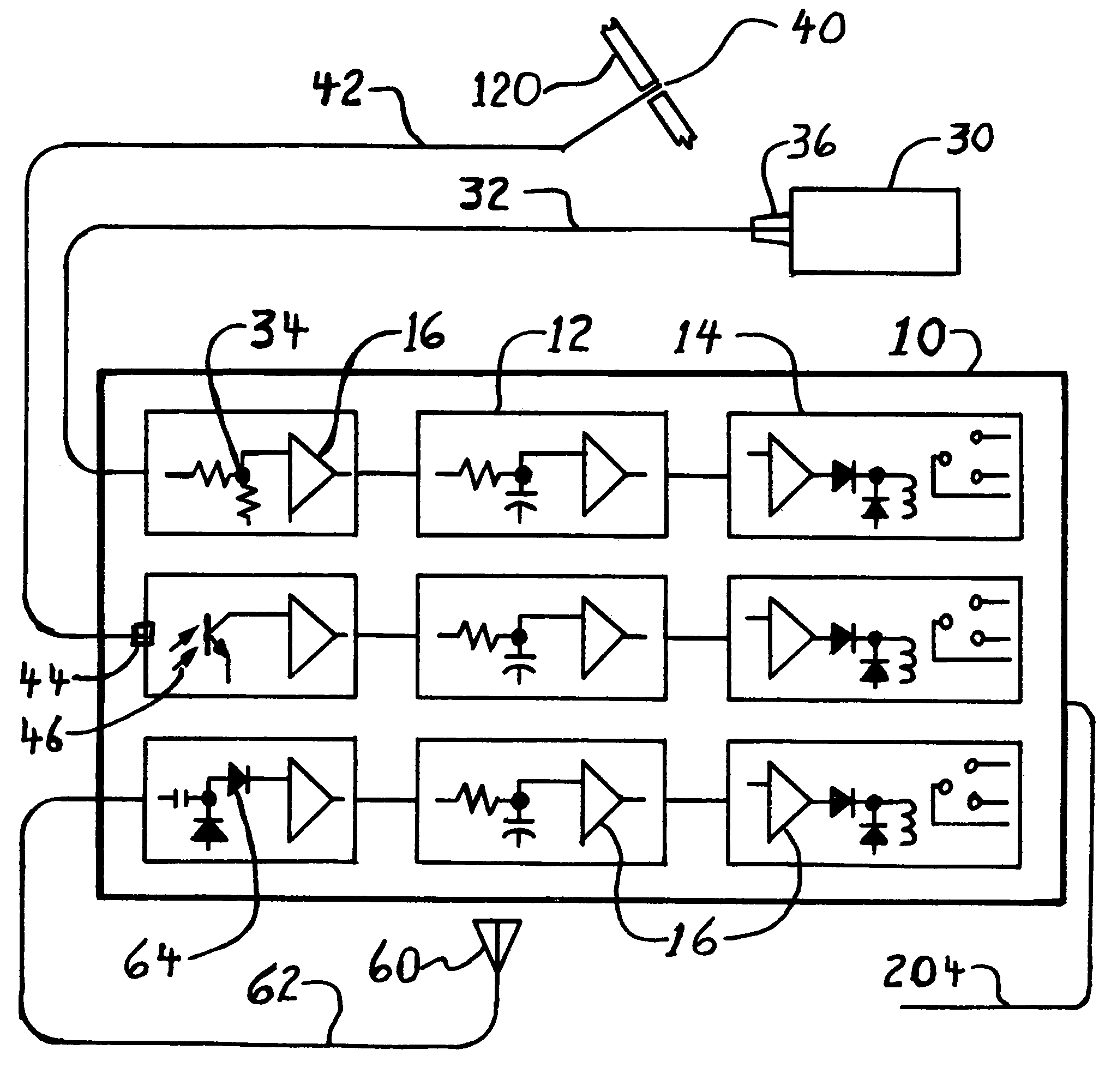
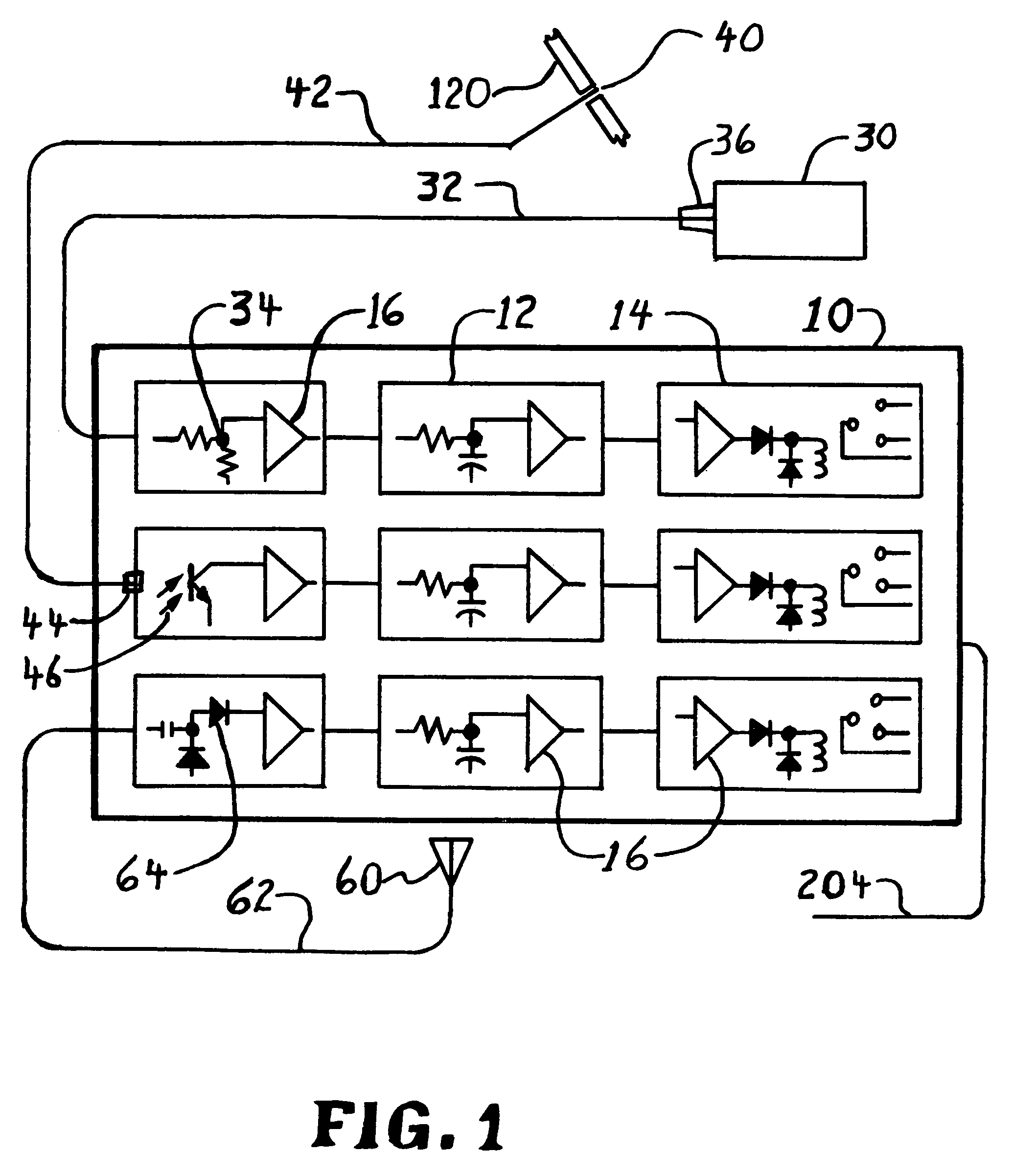
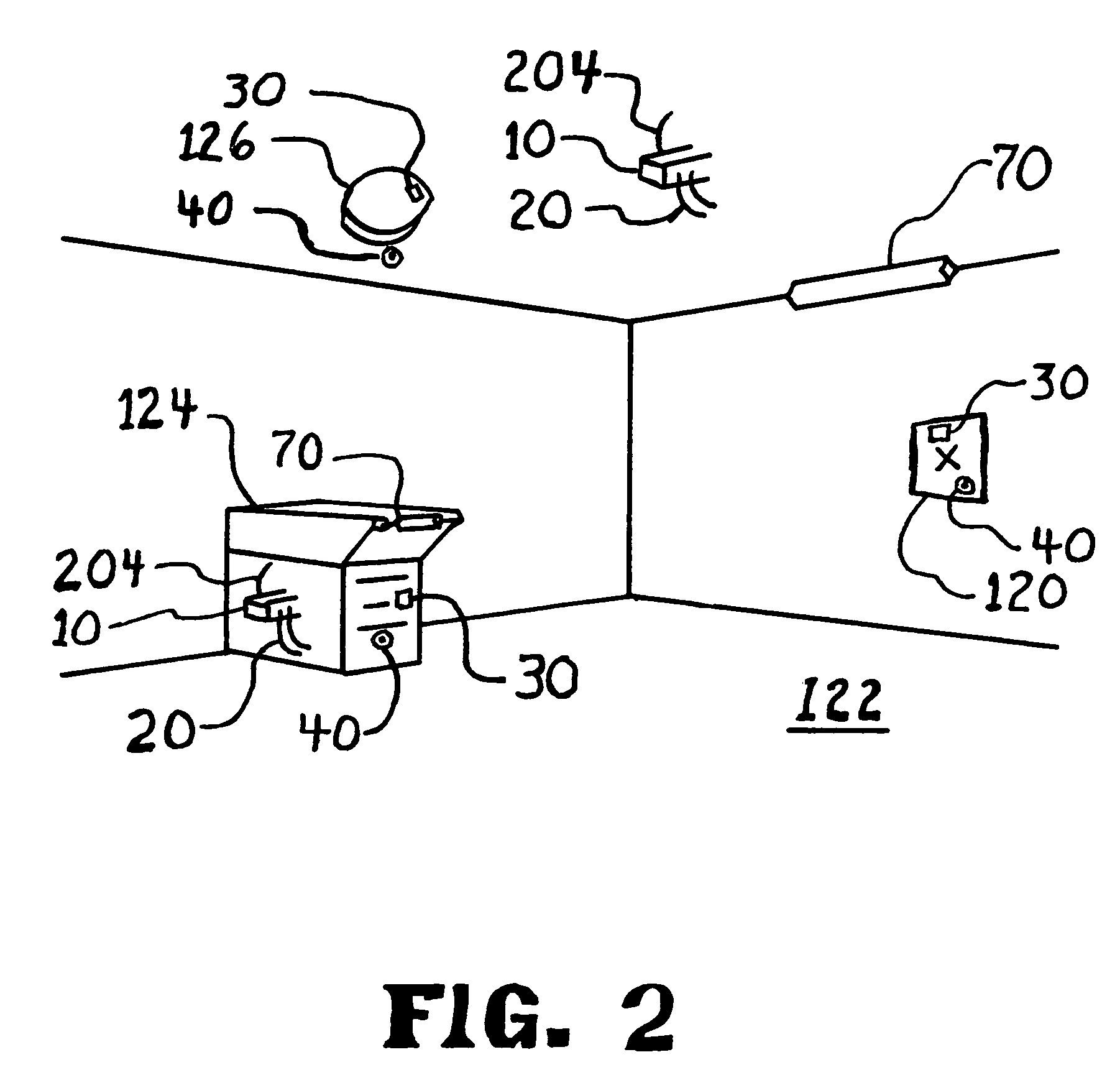
[0054]FIG. 1 shows a schematic of the alarm apparatus 10. The three features (remote monitors) of this invention are: a light detector using a Fiber optic cable 42, a light sensor 30, and radio detector 64 with a remote antenna 60. Each uses a delay timer 12.

[0055]In a preferred embodiment, the alarm apparatus 10 will contain one or more of the three features. An application may have multiple cases of any one feature. Each feature will have a remote monitor and a delay timer 12, which will drive an isolated alarm output 14.

[0056]In a preferred embodiment, the alarm apparatus 10 monitors ambient light at a remote location and trips the alarm output 14 if the ambient light level drops to a pre determined value for a predetermined length of time. In one embodiment a light sensor 30 monitors the ambient light sending the signal through wiring 32 and / or 36 to the voltage divider 34. The light sensor 30 may be thin and flexible and may be a surface mounted photo-resistor or a solar cell

[0...


PUM


Abstract

An alarm apparatus for detecting an intrusion or compromise situation upon critical equipment or private areas. The apparatus detects an unauthorized radio transmitter (like a wireless camera), or the covering of a critical piece of equipment. Fiber optics, solar cells and special radio antennas are used to detect intrusion remotely and a delay timer will allow normal activity to occur, while reducing false alarms. This alarm apparatus will notify an existing system of the intrusion or compromise when limits are exceeded. This alarm apparatus also addresses privacy concerns of wireless cameras and recording devices in areas like changing rooms, bathrooms, or boardrooms. The apparatus addresses security issues for critical devices like smoke alarms and ATM machines.

Description

CROSS-REFERENCE TO RELATED APPLICATIONS[0001](not applicable)FEDERALLY SPONSORED RESEARCH[0002](not applicable)SEQUENCE LISTING[0003](not applicable)BACKGROUND OF THE INVENTION[0004]1. Field of the Invention[0005]This alarm apparatus involves alarm systems, fiber optics, basic electronics, light sensors, and radio frequency detection. The issues are protection of privacy and security of data and equipment.[0006]2. Background of the Related Art[0007]The privacy of the individual is being compromised by new wireless video cameras. They are being used illegally or improperly in or around private places such as changing rooms, bathrooms, motel rooms, and in public places like ATM machines and showers. Locating these have been accidental or at great cost.[0008]U.S. Pat. No. 6,021,269 instructs that radiation transmitting devices (“Bugs”) may be located by searching the area with specialized equipment. These “bugs” are a threat to the privacy of the individual and businesses. Leaky data c...

Claims


Application Information

Patent Timeline
Patent Type & Authority Patents(United States)
IPC IPC(8): G08B21/00
CPCG08B13/1895G07F19/207
Inventor MARSHALL, CRANBROOK
Owner MARSHALL CRANBROOK
Why Eureka
Try Eureka