Apparatus and method for automatically correcting bias voltage for carrier suppressed pulse generating modulator

a technology of suppressed pulses and automatic correction, which is applied in the direction of optical transmission with multiple stages, optical elements, instruments, etc., can solve problems such as deteriorating system performance, and achieve the effect of stabilizing bias voltag

Inactive Publication Date: 2006-07-11
ELECTRONICS & TELECOMM RES INST
View PDF5 Cites 3 Cited by
  • Summary
  • Abstract
  • Description
  • Claims
  • Application Information

AI Technical Summary

Benefits of technology

[0012]Accordingly, the present invention has been made keeping in mind the above problems occurring in the prior art, and an object of the present invention is to provide an apparatus and method for automatically correcting a bias voltage for a carrier suppressed pulse generating modulator using the phase distribution of the output pulse, which automatically detects an optimal bias voltage for the carrier suppressed pulse generating modulator used in CSRZ modulation, and stabilizes the bias voltage.
[0013]In order to accomplish the above object, the present invention provides a method of automatically correcting a bias voltage for a modulator used to generate carrier suppressed pulses, the modulator receiving a continuous laser beam and generating the carrier suppressed pulses, the method comprising the steps of a) setting an optimal bias voltage for the modulator to a bias voltage that is obtained when mean power of an optical signal output from the modulator is highest; b) applying the set optimal bias voltage to the modulator; and c) detecting variations in phase of the output optical signal of the modulator according to variations in the bias voltage during an operation of the modulator, and maintaining the set optimal bias voltage by increasing or decreasing the bias voltage applied to the modulator on the basis of the detected phase variations, thus stabilizing the bias voltage.

Problems solved by technology

Accordingly, an optical transmission signal is distorted due to the DC bias drift, so that an extinction ratio is deteriorated and unstable power is output, thus deteriorating the performance of the system.

Method used


Image

  • Apparatus and method for automatically correcting bias voltage for carrier suppressed pulse generating modulator
  • Apparatus and method for automatically correcting bias voltage for carrier suppressed pulse generating modulator
  • Apparatus and method for automatically correcting bias voltage for carrier suppressed pulse generating modulator

Examples


Embodiment Construction

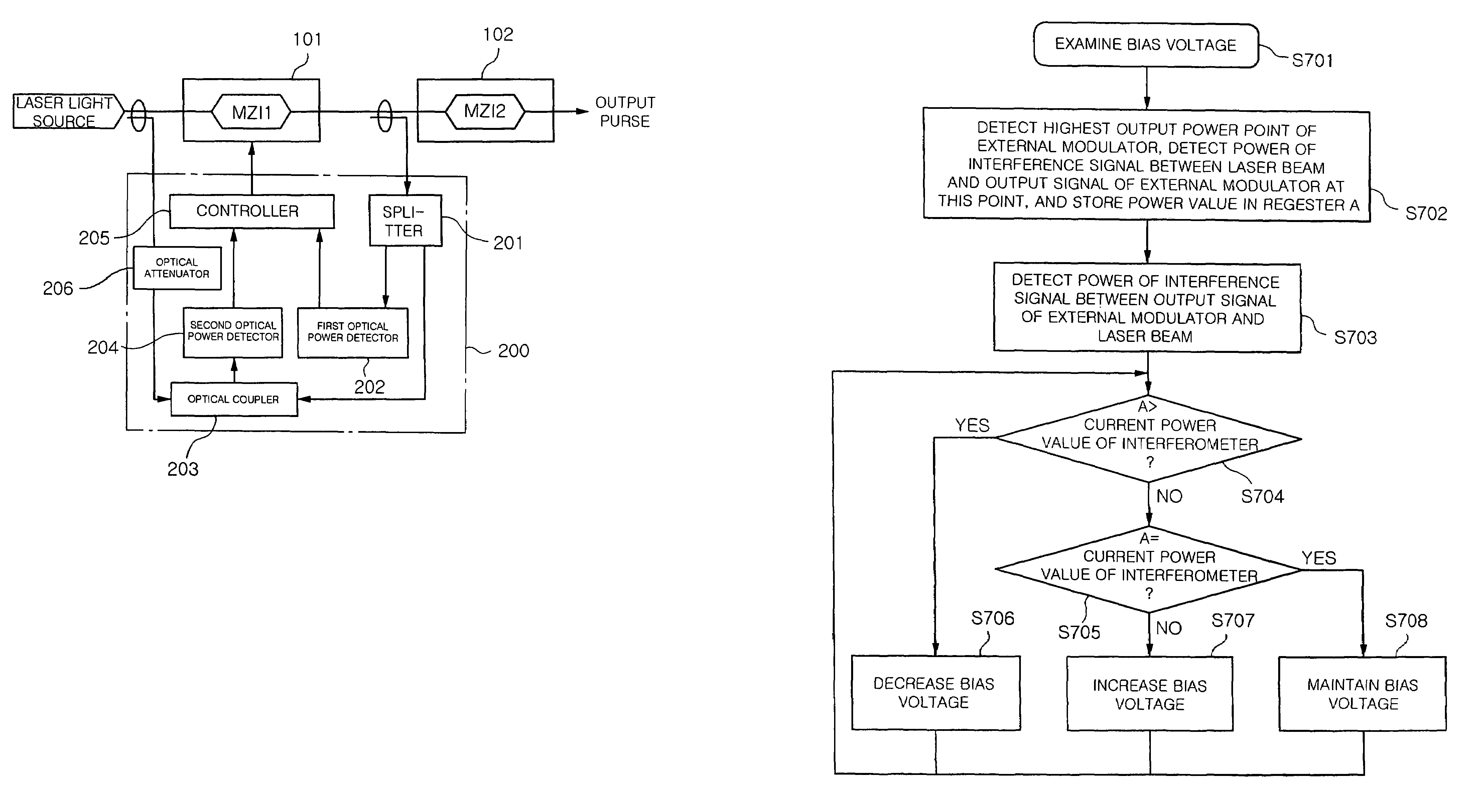
[0029]Hereinafter, an apparatus and method for automatically correcting a bias voltage for a carrier suppressed pulse generating modulator using the phase distribution of the output pulse, according to embodiments of the present invention will be described in detail with reference to the attached drawings.

[0030]Reference now should be made to the drawings, in which the same reference numerals are used throughout the different drawings to designate the same or similar components.

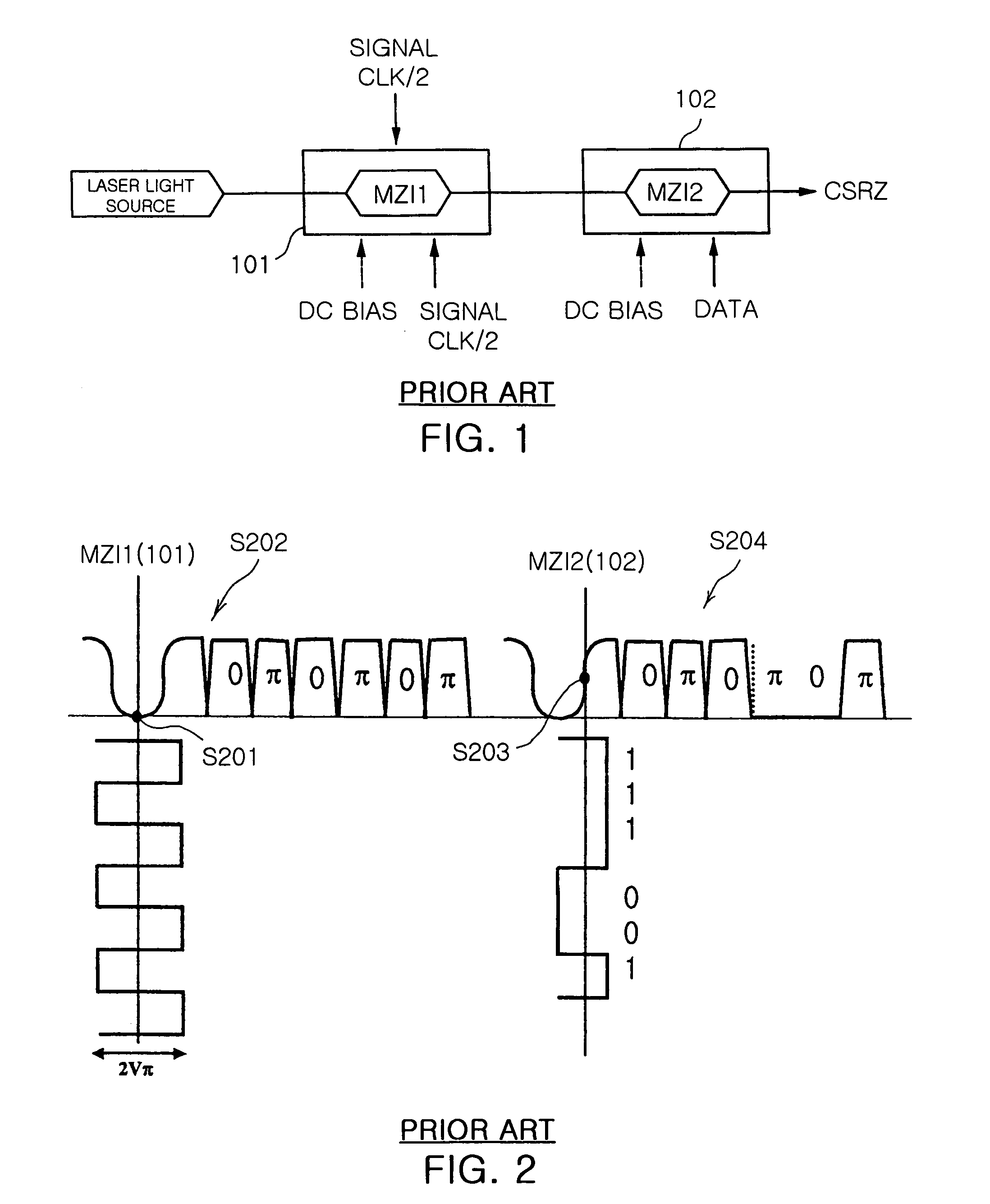
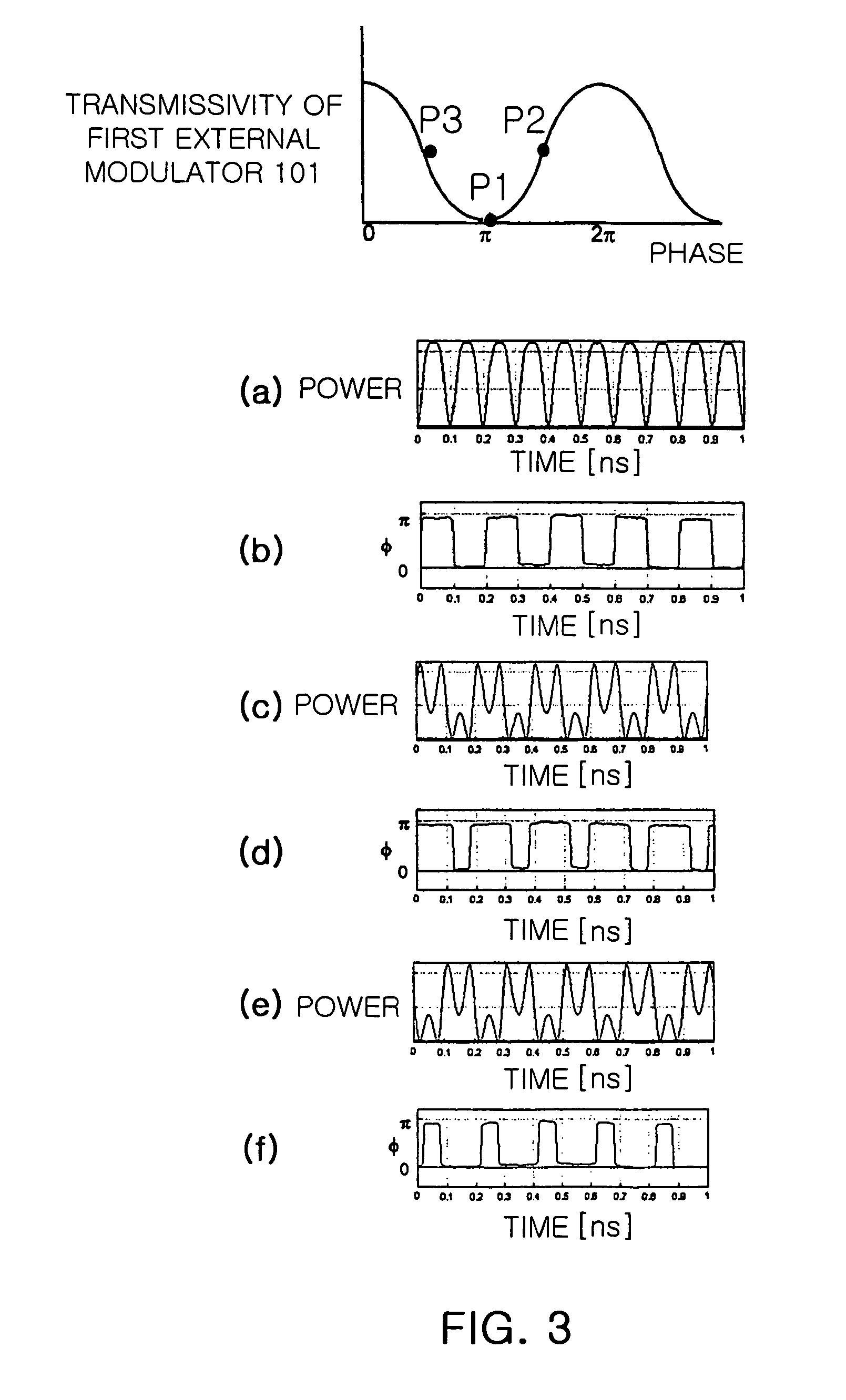
[0031]FIGS. 3(a) to (f) is a graph showing a relationship between variations in the position of a DC bias voltage and variations in an output signal of a CSRZ modulator, that is, the first external modulator 101 shown in FIG. 1. Referring to FIGS. 3(a) to (f), when the bias voltage is located at an optimal point P1, the pulse shape of the output signal of the first external modulator 101 and the phase variation thereof are ideally shown as represented in graphs of FIGS. 3(a) and (b), respectively.

[0032]Howeve...


PUM

PropertyMeasurementUnit
bias voltageaaaaaaaaaa
optimal bias voltageaaaaaaaaaa
bias voltagesaaaaaaaaaa

Abstract

The present invention relates to an apparatus and method for automatically correcting a bias voltage for a carrier suppressed pulse generating modulator using the phase distribution of the output pulses, which automatically detects an optimal bias voltage for the carrier suppressed pulse generating modulator and stabilizes the bias voltage.In the bias voltage automatic correction method and apparatus of the present invention, an optimal bias voltage for the modulator is set to a bias voltage that is obtained when mean power of an optical signal output from the modulator is highest. The varying direction of the bias voltage is detected on the basis of the phase variations in the output optical signal of the modulator according to the bias voltage variations is detected, and the bias voltage is corrected oppositely to the varying direction of the bias voltage.

Description

BACKGROUND OF THE INVENTION[0001]1. Field of the Invention[0002]The present invention relates, in general, to an apparatus and method for automatically correcting a bias voltage for a carrier suppressed pulse generating modulator using the phase distribution of the output pulse, which performs automatic control to automatically detect an optimal bias voltage for the carrier suppressed pulse generating modulator used in a carrier suppressed return-to-zero modulator and to maintain the optimal bias voltage during the operation of the modulator.[0003]2. Description of the Related Art[0004]Generally, in a long distance optical transmission system using Wavelength Division Multiplexing (WDM), the modulation of a transmission signal has been performed by a Non-Return-to-Zero (NRZ) modulation method using a Mach-Zehnder type external modulator. An external modulator used in this case exhibits a phenomenon (a DC bias drift) in which a transfer curve moves laterally due to the variations in ...

Claims


Application Information

Patent Timeline
Patent Type & Authority Patents(United States)
IPC IPC(8): G02B26/00H04B10/18G02F1/00G02F1/01H04B10/155
CPCH04B10/505H04B10/5051H04B10/50575H04B10/508H04B10/5162H04B10/5165H04B10/50595G02F1/0123H04B2210/003E04H13/006
Inventor JANG, YOUN SEONKIM, KWANG JOONLEE, JYUNG CHANMYONG, SEUNG IL
Owner ELECTRONICS & TELECOMM RES INST
Why Eureka
Try Eureka