High efficiency collector for laser plasma EUV source

a collector optics and laser plasma technology, applied in the field of collector optics for light sources, can solve the problem that the best si/mo coating on the collector optics only reflects

Inactive Publication Date: 2006-07-11
NORTHROP GRUMAN CORP
View PDF8 Cites 45 Cited by
  • Summary
  • Abstract
  • Description
  • Claims
  • Application Information

AI Technical Summary

Benefits of technology

[0014]In accordance with the teachings of the present invention, collector optics are disclosed that provides an increase of the collection of light. In one embodiment, the collector optics is part of an EUV radiation source for collecting EUV radiation. The collector optics includes a reflector, such as an elliptical dish reflector. The light generated at a focal point of the reflector is reflected by the reflector and is directed to a collection location. An annular reflector is provided around an outer edge of the dish reflector to collect more of the light that may otherwise be lost. The light reflected by the annular reflector is directed to a center reflector positioned between the focal point of the dish reflector and the collection location to redirect the light reflected by the annular reflector to be within a predetermined collection zone and angle.

Problems solved by technology

However, the best Si / Mo coating on the collector optics only reflects about 70% of the EUV radiation impinging thereon, even at its theoretical maximum performance.

Method used


Image

  • High efficiency collector for laser plasma EUV source
  • High efficiency collector for laser plasma EUV source
  • High efficiency collector for laser plasma EUV source

Examples


Embodiment Construction

[0021]The following discussion of the embodiments of the invention directed to collector optics for an EUV radiation source is merely exemplary in nature and is in no way intended to limit the invention or its application or uses. For example, the discussion below specifically talks about the collector optics being used in an EUV radiation source. However, as will be appreciated by those skilled in the art, the collector optics will have application for other systems for collecting other wavelengths of light.

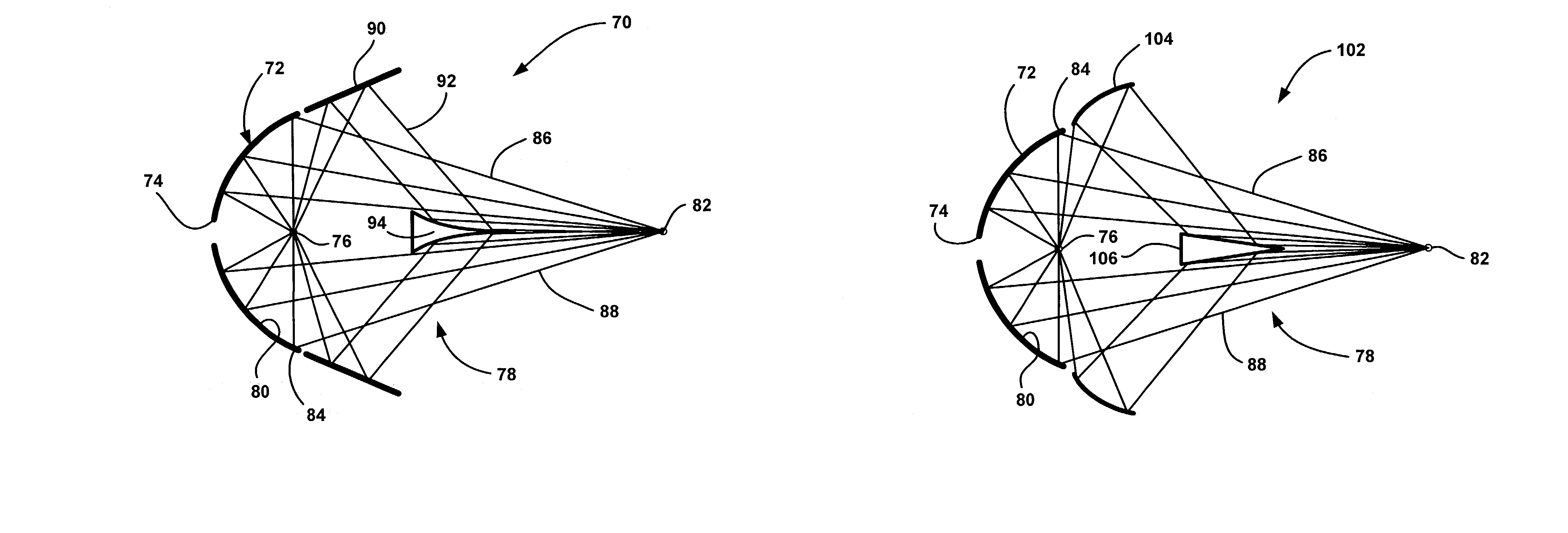
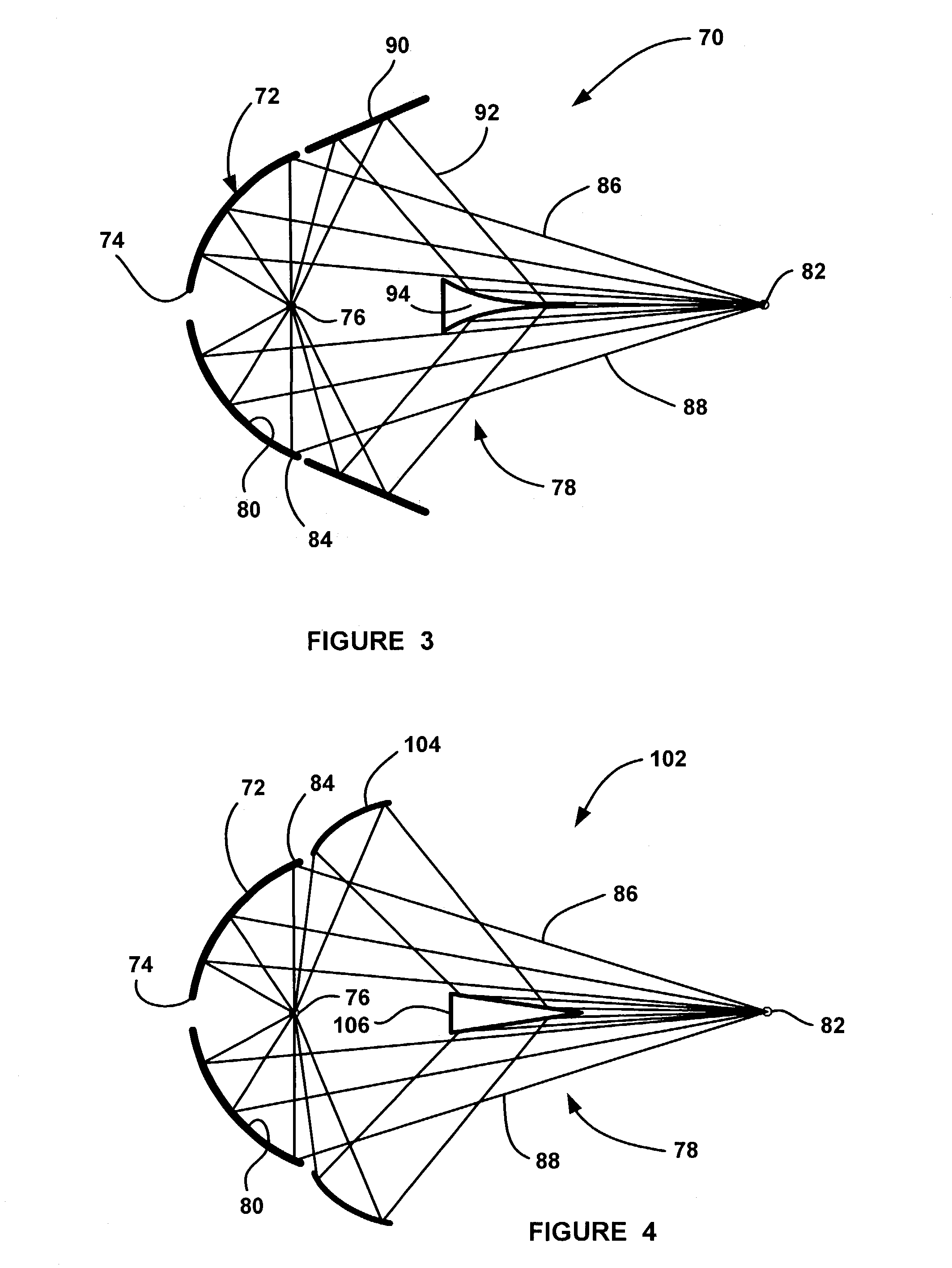
[0022]FIG. 3 is a cross-sectional plan view of collector optics 70 that is useable in the EUV radiation source 10, discussed above, according to an embodiment of the present invention. The collector optics 70 includes an elliptical dish reflector 72 including a center opening 74 through which a laser beam propagates to a target area 76, as discussed above. EUV radiation 78 is generated at the target area 76, reflected off of an inner surface 80 of the dish reflector 72 and is di...


PUM

PropertyMeasurementUnit
diameteraaaaaaaaaa
sizeaaaaaaaaaa
angle of reflectionaaaaaaaaaa

Abstract

Collector optics (70) for an EUV radiation source (10) for collecting EUV radiation (78). The collector optics (70) includes an elliptical dish reflector (72) where light generated at a focal point (76) of the reflector (72) is collected by the reflector (72) and is directed to a collection location (82). A frustal annular reflector (90) is positioned around an outer edge (84) of the dish reflector (72) to collect more of the EUV radiation (78) that may otherwise be lost. The radiation (78) reflected by the annular reflector (90) is directed to a center axicon reflector (94) positioned between the focal point (76) of the dish reflector (72) and the collection location (82) to redirect the radiation (78) reflected by the annular reflector (90) to be within a predetermined collection angle.

Description

BACKGROUND OF THE INVENTION[0001]1. Field of the Invention[0002]This invention relates generally to collector optics for a light source and, more particularly, to high efficiency collector optics for a laser plasma extreme ultraviolet (EUV) radiation source that collects a high percentage of the generated EUV radiation.[0003]2. Discussion of the Related Art[0004]Microelectronic integrated circuits are typically patterned on a substrate by a photolithography process, well known to those skilled in the art, where the circuit elements are defined by a light beam propagating through a mask. As the state of the art of the photolithography process and integrated circuit architecture becomes more developed, the circuit elements become smaller and more closely spaced together. As the circuit elements become smaller, it is necessary to employ photolithography light sources that generate light beams having shorter wavelengths and higher frequencies. In other words, the resolution of the photo...

Claims


Application Information

Patent Timeline
Patent Type & Authority Patents(United States)
IPC IPC(8): G02B5/08G21K1/06G02B5/10G03F7/20G21K5/00H01L21/027H05H1/24
CPCB82Y10/00G03F7/70175G03F7/70033
Inventor ARENBERG, JONATHAN W.
Owner NORTHROP GRUMAN CORP
Why Eureka
Try Eureka