
Beam conditioning system

a beam conditioning and beam technology, applied in the field of xray optical systems, can solve the problems of low efficiency, low efficiency, and limited ability of multilayer optics to provide a high capture angle, and achieve the effect of high-flux operations

Active Publication Date: 2006-07-11
OSMIC INC
View PDF23 Cites 21 Cited by
  • Summary
  • Abstract
  • Description
  • Claims
  • Application Information

AI Technical Summary

Benefits of technology

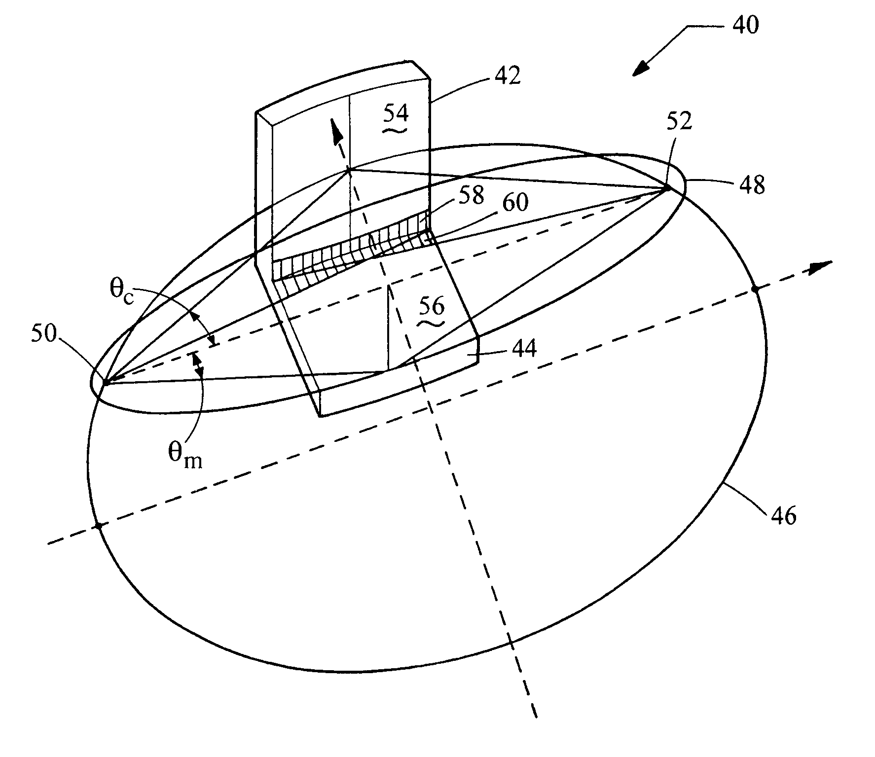
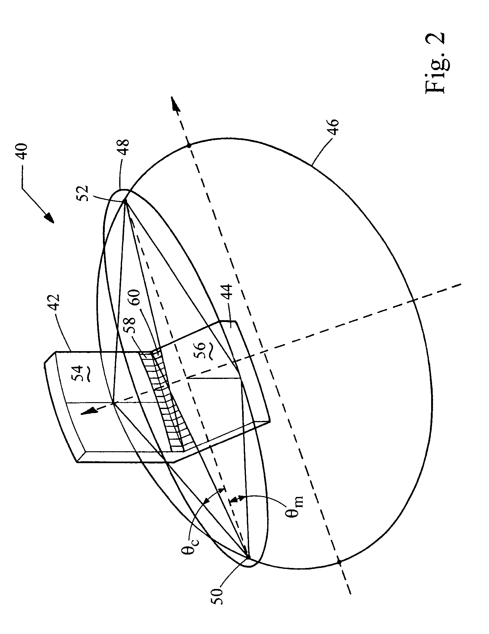
This configuration significantly improves x-ray beam conditioning by achieving higher flux and capture angles, surpassing the limitations of traditional systems, particularly in applications requiring high convergence and flux, as demonstrated by superior efficiency calculations compared to single-element and pure multilayer optics.

Problems solved by technology

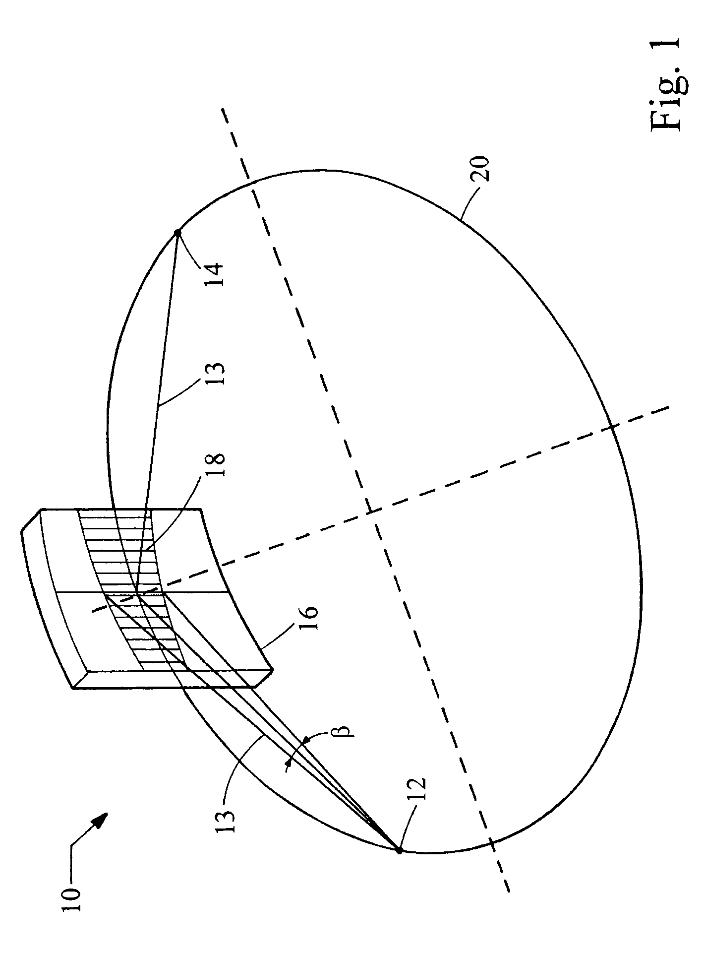
Although the use of multilayer mirrors in a Kirkpatrick-Baez configuration provides increased efficiency, this type of system is not optimal because mirrors positioned at different distances from the source have different capture angles (i.e., a mirror positioned further from the source has lower efficiency), and, additionally, the beam convergence and image size are different in two planes, resulting in a phenomenon known as anamorphotism.
These applications demand a high flux, but a multilayer optic has limited capabilities to provide a high capture angle because of its relatively large d-spacing.
However, crystals have several drawbacks that have heretofore limited their application in certain x-ray related fields.
Mosaic crystals have a modest reflectivity and a large penetration depth, which is not favorable in applications requiring sharp focusing.
Both types of crystals have a limited acceptance in the axial plane (plane perpendicular to the diffraction plane), and this acceptance drops significantly when an x-ray is not parallel to the diffraction plane.
This last feature makes optical systems with two diffractive elements with small d-spacing and narrow rocking curve ineffective.
These limiting factors have heretofore rendered optics having crystal combinations ineffective in particular x-ray applications.

Method used


Image

  • Beam conditioning system
  • Beam conditioning system
  • Beam conditioning system

Examples


Embodiment Construction

[0018]An analysis of the efficiency of various diffractive x-ray optical elements provides a basis for the understanding of the present invention. For simplicity, consider a single diffractive element with a cylindrical reflecting surface and with a capability to focus x-rays from a point source to the point image in the diffraction plane. Examples of such diffractive elements are Johansson crystals and elliptical multilayers with a proper grading of d-spacing. The capability of these optical elements to accept and redirect x-rays from a monochromatic x-ray source can be described as:

ε=f·α·β·R,  (2)

where f is a factor describing from which portion of the source size a diffractive element can use radiation, α and β are the acceptance angles in the diffraction and axial planes, respectively, and R is the element reflectivity.

[0019]The efficiency of the source focal spot usage f can be calculated as a convolution of a source spatial intensity distribution and a diffractive element angu...


PUM


Abstract

The present invention provides an x-ray beam conditioning system with a Kirkpatrick-Baez diffractive optic including two optical elements, of which one of the optical elements is a crystal. The elements are arranged in a side-by-side configuration. The crystal can be a perfect crystal. One or both diffractive elements can be mosaic crystals. One element can be a multilayer optic. For example, the multilayer optic can be an elliptical mirror or a parabolic mirror with graded d-spacing. The graded d-spacing can be either lateral grading or depth grading, or both.

Description

RELATED APPLICATION[0001]This application claims the benefit of U.S. Provisional Application No. 60 / 478,460, filed Jun. 13, 2003, the entire contents of which are incorporated herein by reference.BACKGROUND[0002]The present invention relates generally to an x-ray optical system for conditioning an x-ray beam. More particularly, the present invention relates to a optical system for reflecting an x-ray beam in two directions.[0003]There are a number of x-ray applications that require the use of a two dimensional conditioned x-ray beam. For example, medical radiotherapy systems utilize x-ray beams to destroy cancerous tissue, x-ray diffraction or microdiffraction analysis systems channel x-ray radiation at a sample crystal generating a diffraction pattern indicative of a lattice structure, and x-ray fluorescence and spectroscopy systems employ directed and conditioned x-ray beams.[0004]A Kirkpatrick-Baez optical configuration has been proposed to reflect an x-ray beam in two directions...

Claims


Application Information

Patent Timeline
Patent Type & Authority Patents(United States)
IPC IPC(8): G21K1/06G02B26/08
CPCB82Y10/00G21K1/06G21K1/062G21K2201/064G21K2201/061G21K2201/062
Inventor VERMAN, BORISHARADA, JIMPEI
Owner OSMIC INC
Learn More