Toroidal continuously variable transmission

a continuously variable transmission and rotating shaft technology, applied in the direction of friction gearings, gearing elements, gearings, etc., can solve the problems of undesirable vertical horizontal displacement of the power roller, and small error in relative position between the power roller and the respective disk, so as to reliably support the load acting, low manufacturing cost, and simple and inexpensive

Inactive Publication Date: 2006-07-18
NISSAN MOTOR CO LTD
View PDF13 Cites 4 Cited by
  • Summary
  • Abstract
  • Description
  • Claims
  • Application Information

AI Technical Summary

Benefits of technology

[0006]In one aspect, the present invention provides a toroidal continuously variable transmission having a simple and inexpensive power roller support structure, which is capable of properly restricting or limiting a horizontal displacement of a roller-and-cage bearing assembly relative to a trunni

Problems solved by technology

Owing to deformation of the input and output disks during power transmission, or in presence of a slight misalignment after installation, there is a slight error in relative position between the power roller and the respective disk.
In this case, oscillating motion of the eccentric pivot causes the horizontal displacement of the power roller.
At the same time, the oscillating motion of the eccentric pivot also causes an undesirable vertical displacement of the power roller.
Thus, the undesirable vertical displacement results in a slight offset of the power roller from the center of rotation of the disks.
This causes undesirable transmission-ratio changing.
During power transmission, slight errors in relative position between the power roller and the respective disk repeatedly occur owing to de

Method used


Image

  • Toroidal continuously variable transmission
  • Toroidal continuously variable transmission
  • Toroidal continuously variable transmission

Examples


Embodiment Construction

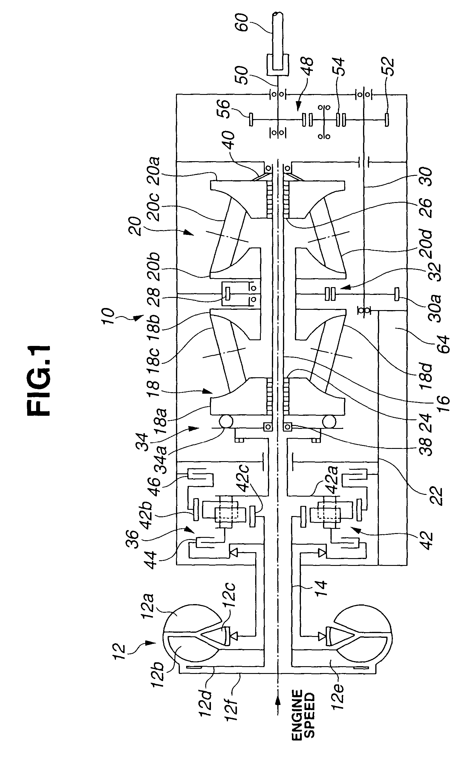
[0015]Referring now to the drawings, particularly to FIG. 1, a toroidal continuously variable transmission 10 of the embodiment is combined with a lock-up torque converter 12. As seen from the left-hand side of FIG. 1, engine torque (driving torque) is transmitted via lock-up torque converter 12 to an input shaft 14 of toroidal CVT 10. Lock-up torque converter 12 is comprised of a pump impeller 12a, a turbine runner 12b, a stator 12c, a lock-up clutch 12d, an apply-pressure chamber 12e, a release-pressure chamber 12f, and the like. Transmission input shaft 14 is rotatably located at the center of lock-up torque converter 12d. Input shaft 14 is connected to a forward and reverse changeover mechanism 36. Forward and reverse changeover mechanism 36 is comprised of a planetary gearset 42, a forward clutch 44, and a reverse brake 46. Planetary gearset 42 consists of a pinion carrier 42a with two planet pinions, a ring gear 42b being in meshed-engagement with these planet pinions, and a s...


PUM


Abstract

In a toroidal continuously variable transmission, a roller-and-cage bearing assembly is interleaved between a power-roller outer ring and a trunnion power-roller accommodating portion to permit a parallel translation of a power roller in an axial direction of input and output disks. A cage of the roller-and-cage bearing assembly is formed with an oval slotted hole. A disk-shaped member is attached to the trunnion power-roller accommodating portion. The slotted hole and the disk-shaped member are fitted to each other to define a predetermined clearance that limits a displacement of the roller-and-cage bearing assembly in a direction perpendicular to both a rotation axis of the power roller and a trunnion axis to a set displacement.

Description

REFERENCE TO RELATED APPLICATIONS[0001]This application is a continuation-in-part of application Ser. No. 10 / 057,966, filed Jan. 29, 2002, now abandoned, the content of which is incorporated herein in its entirety.FIELD OF THE INVENTION[0002]The present invention relates to a toroidal continuously variable transmission, and specifically to a support for a power roller interposed between input and output disks of a toroidal continuously variable transmission.DESCRIPTION OF THE RELATED ART[0003]In recent years, to meet demands for increased shift comfort, improved driveability, and reduced fuel consumption and exhaust emissions, there have been proposed and developed various continuously variable transmissions, such as a segmented metal belt-drive continuously variable transmission and a toroidal continuously variable transmission often abbreviated to “toroidal CVT”, in which a transmission ratio is steplessly variable within limits. Toroidal CVTs in which engine power (torque) is tra...

Claims


Application Information

Patent Timeline
IPC IPC(8): F16H15/38F16H61/664
CPCF16H15/38F16H61/664F16H61/6648Y10T74/18184Y10T74/18176Y10T74/18182Y10T74/18224
Inventor MORI, HARUHITOSUGIHARA, JUN
Owner NISSAN MOTOR CO LTD
Why Eureka
Try Eureka