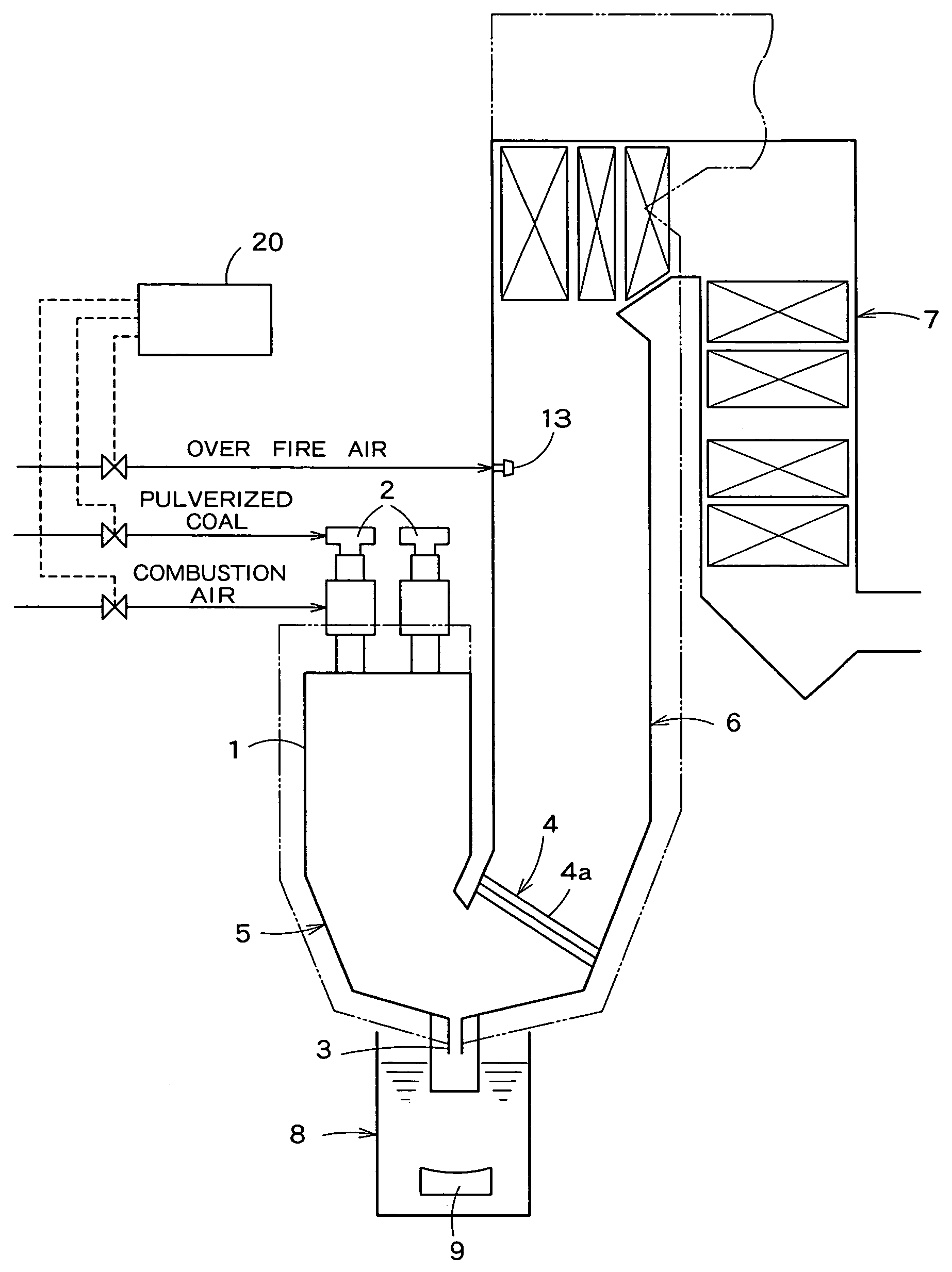
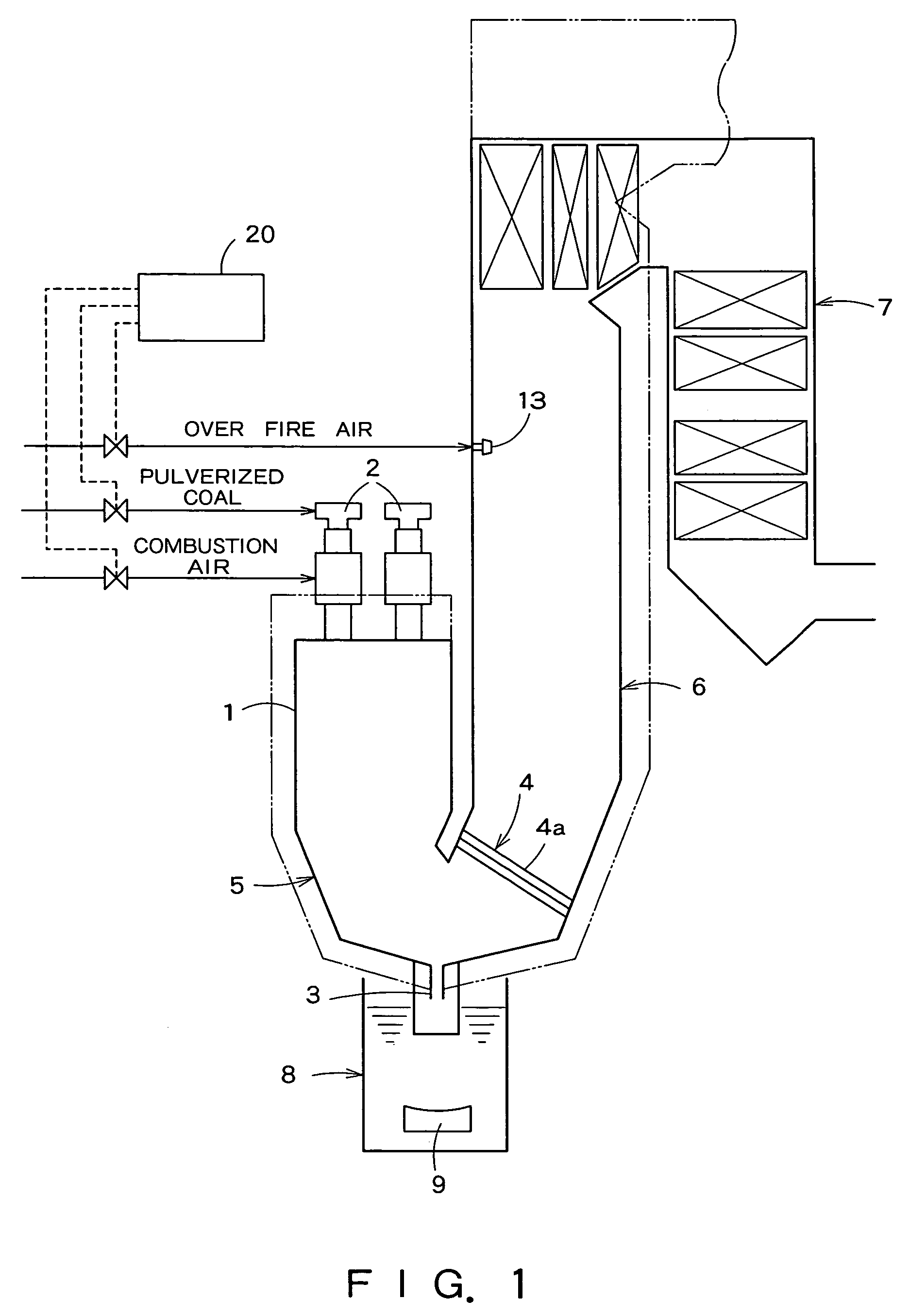
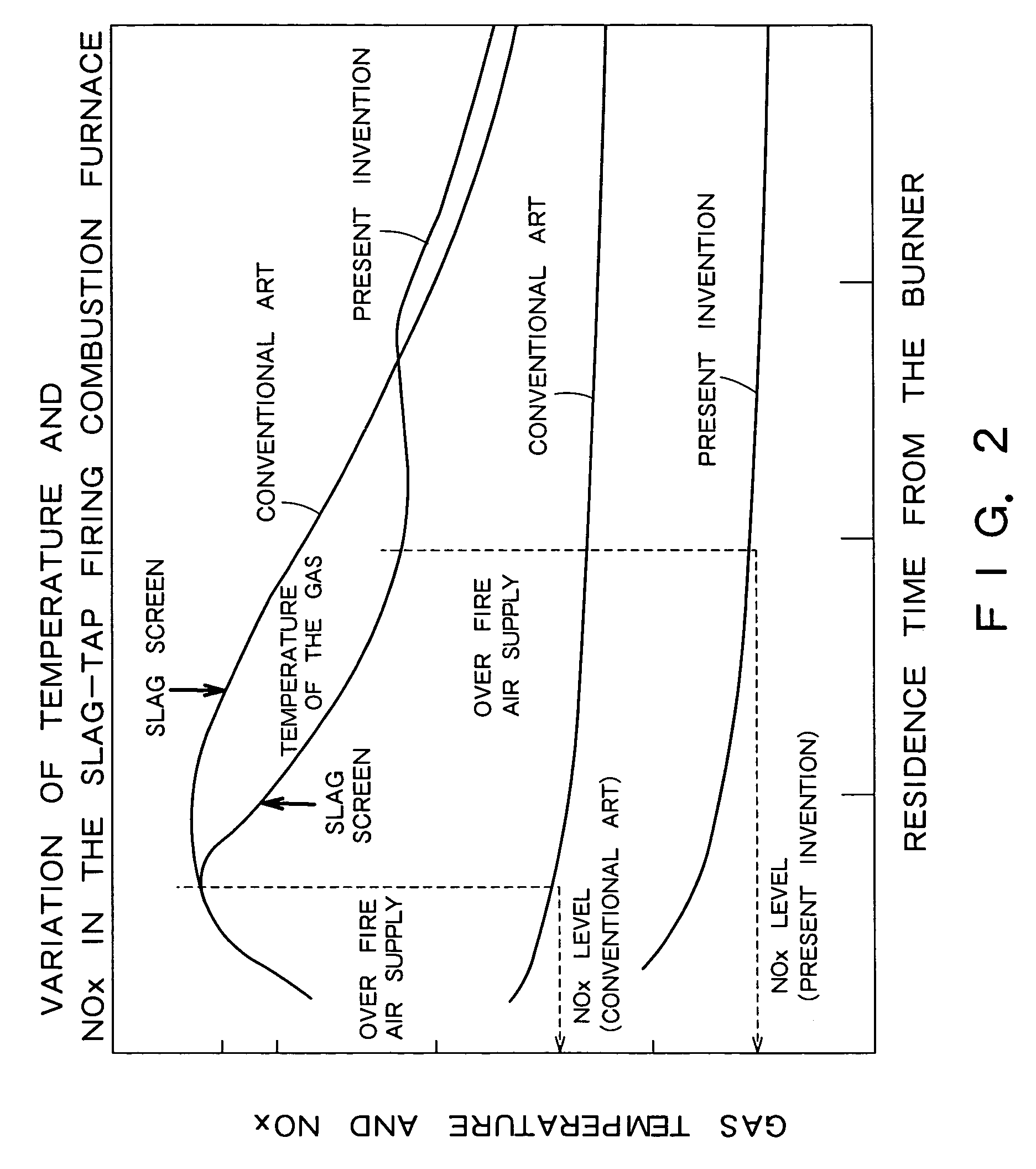
[0017]According to the present invention, a method of operating a U-type slag-tap firing boiler, comprises: forming a combustion furnace in a volume so that a temperature of a gas flowing through a slag screen separating a combustion furnace and a radiant furnace disposed below the combustion furnace is maintained in a temperature range that ensures a
normal functioning of the slag screen even if an air is supplied through a burner into the combustion furnace at an air ratio below 1; and supplying an air through the burner into the combustion furnace such that the air ratio is below 1, burning a pulverized coal in a fuel-rich combustion mode in the combustion furnace to
crate a
reducing atmosphere in the combustion furnace and heating an interior of the combustion furnace at a temperature around a
fluid temperature, so as to reduce
NOx generation.
[0024]Preferably, a
heat flux transferred through a screen
tube forming the slag screen is calculated from a difference between temperatures measured respectively by a
thermometer disposed near an inlet of the screen tube and a
thermometer disposed near an outlet of the screen tube, it is decided that the slag screen is plugged when a calculated
heat flux is smaller than a predetermined
heat flux, and a
fluid temperature lowering agent (flux: limestone or
hematite) for lowering a fluid temperature is supplied into the combustion furnace to lower a fluid temperature of slag so that a slag melts and flows easily, an amount of slag deposited on the slag screen decreases and a plug of the slag screen is unclogged when it is decided that the slag screen is plugged.
[0028]Preferably, the U-type slag-tap firing boiler further comprises a
nozzle to supply an over fire air into the radiant furnace to achieve a complete combustion for a further reduction of
NOx emission.
[0029]Preferably, the U-type slag-tap firing boiler further comprises thermometers disposed near an inlet and an outlet, respectively, of the screen tube, wherein the controller calculates a heat flux transferred through the screen tube from a difference between temperatures measured respectively by the thermometers disposed near the inlet and the outlet of the screen tube, decides that the slag screen is plugged when a calculated heat flux is smaller than a predetermined heat flux, increases the air supply rate at which an air is supplied through the burner into the combustion furnace to increase the air ratio beyond a predetermined air ratio so that the heat flux transferred through the screen tube is increased to or above a predetermined heat flux, so as to unclog a plug of the slag screen.
[0031]Preferably, the U-type slag-tap firing boiler further comprises thermometers disposed near an inlet and an outlet, respectively, of the screen tube, wherein the controller calculates a heat flux transferred through the screen tube from a difference between temperatures respectively measured by the thermometers disposed near the inlet and the outlet of the screen tube while the U-type slag-tap firing boiler is in a partial-load operation, decides that the slag screen is plugged when a calculated heat flux is smaller than a predetermined heat flux, increases the air supply rate at which an air is supplied through the burner into the combustion furnace and the
fuel supply rate at which a fuel is supplied into the combustion furnace to raise a temperature of a gas flowing through the slag screen so that the heat flux transferred through the screen tube is increased to or above the predetermined heat flux, so as to unclog a plug of the slag screen.
[0033]Preferably, the U-type slag-tap firing boiler further comprises thermometers disposed near an inlet and an outlet, respectively, of the screen tube, and the controller calculates a heat flux transferred through the screen tube from a difference between temperatures respectively measured by the thermometers disposed near the inlet and the outlet of the screen tube, decides that the slag screen is plugged when a calculated heat flux is smaller than a predetermined heat flux, and supplies a fluid temperature lowering agent into the combustion furnace to lower a fluid temperature of slag so that a slag melts and flows easily, thereby, an amount of slag deposited on the slag screen decreases and a plug of the slag screen is unclogged.

