Cooling device high voltage electrical unit for motor of vehicle, and hybrid vehicle

a high-voltage electrical and motor-powered technology, applied in electric devices, cell components, electrochemical generators, etc., can solve the problems of reducing the charging and discharging efficiency of batteries, increasing the amount of heat emitted, and affecting the efficiency so as to achieve efficient cooling of high-voltage electrical units

Active Publication Date: 2006-07-18
HONDA MOTOR CO LTD
View PDF25 Cites 98 Cited by
  • Summary
  • Abstract
  • Description
  • Claims
  • Application Information

AI Technical Summary

Benefits of technology

[0012]In consideration of the above circumstances, an object of the present invention is to efficiently cool down a high voltage electrical unit without degrading utility of the vehicle.
[0016]According to the above structure, the electrical energy storing device, whose control temperature is relatively low among those of the high voltage electrical devices such as the electrical energy storing device and the inverter which are disposed in a concentrated manner, is first cooled, and then the inverter and the downverter, which tend to have a temperature higher than the control temperature of the electrical energy storing device, are cooled at one time; therefore, efficiency of heat exchange can be improved.
[0028]According to the above structure, inductance and resistance can be reduced.
[0031]According to the present invention, because the high voltage electrical devices such as the electrical energy storing device and the inverter which are disposed under the seat in a concentrated manner, a so-called trunk-through configuration can be employed, and degradation of utility can be avoided. Moreover, because the high voltage electrical devices are not disposed in the luggage compartment or under the floor, a luggage compartment and a leg room of sufficient size can be ensured. Furthermore, because the high voltage electrical devices are disposed in the passenger compartment, the upper surfaces of the seats will not be located at a high position, and the passenger will not feel that there is a lack of head clearance even though a minimum ground clearance is ensured.
[0032]In addition, because the high voltage electrical devices such as the battery, which is a high voltage power source, and the inverter, are disposed, with the fan, on the single frame in a concentrated manner, the cooling systems can be unified, and thus a lower cost can be achieved.

Problems solved by technology

The charging and discharging efficiency of a battery may decrease due to high temperature.
An inverter has a permissible high temperature, and the inverter may be damaged when the temperature thereof exceeds the permissible high temperature.
By increasing the capacity of an inverter, the amount of heat emitted from the inverter can be reduced; however, increase in the capacity results in increase in the size and weight of the inverter, which is not preferable in view of installation of the inverter in a vehicle because it is required for an inverter, which is to be installed in a vehicle, to be as small as possible.
However, in the technology disclosed in Japanese Unexamined Patent Application, First Publication No. 2003-79003, because a high voltage electrical unit is installed behind a rear seat, problems are encountered in that the rear seat cannot be folded, the size of a luggage compartment is limited, a point at which the high voltage electrical unit is connected to a structural body part is located far, long lines from a motor are required, a countermeasure for a rear impact must be considered, etc.
Moreover, in the technology disclosed in Japanese Unexamined Patent Application, First Publication No. 2001-233064, because a high voltage electrical device and a high voltage power source are separately disposed, a problem is encountered in that two cooling systems are required.
Furthermore, when a high voltage power source is installed under a floor, as another technology other than those disclosed in Japanese Unexamined Patent Application, First Publication Nos. 2003-79003 and 2001-233064, problems are encountered in that upper surfaces of seats are located at a high position in order to ensure a minimum ground clearance, the passenger may feel that there is a lack of head clearance and uneasiness in getting in and out, a perfect sealing structure with respect to the passenger compartment must be considered, protection against heat of the exhaust system must be considered in the case of a hybrid vehicle, etc.
As explained above, a vehicle provided with a high voltage electrical unit may have degraded utility because the size of the vehicle cannot be significantly increased when compared with an ordinal gasoline vehicle.

Method used


Image

  • Cooling device high voltage electrical unit for motor of vehicle, and hybrid vehicle
  • Cooling device high voltage electrical unit for motor of vehicle, and hybrid vehicle
  • Cooling device high voltage electrical unit for motor of vehicle, and hybrid vehicle

Examples


Embodiment Construction

[0050]The best modes of the present invention will be explained below with reference to FIGS. 1 to 16.

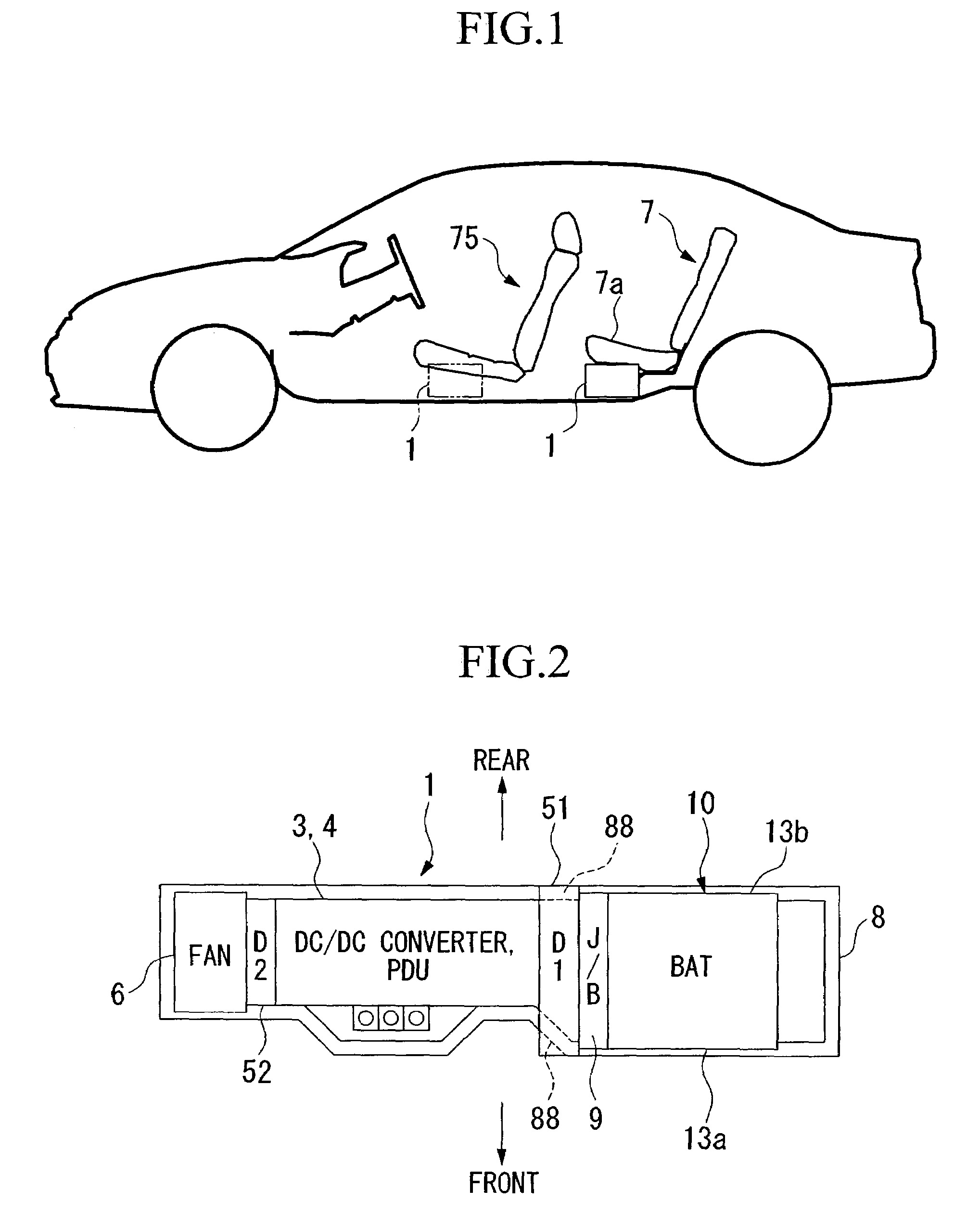
[0051]The vehicle in the following embodiments is a hybrid vehicle which is driven by transmitting at least one of driving powers of an engine and a motor to driving wheels of the vehicle.

[0052]In the following description, the terms such as front, rear, right, and left are defined such that the direction along which the vehicle advances is defined as a forward direction.

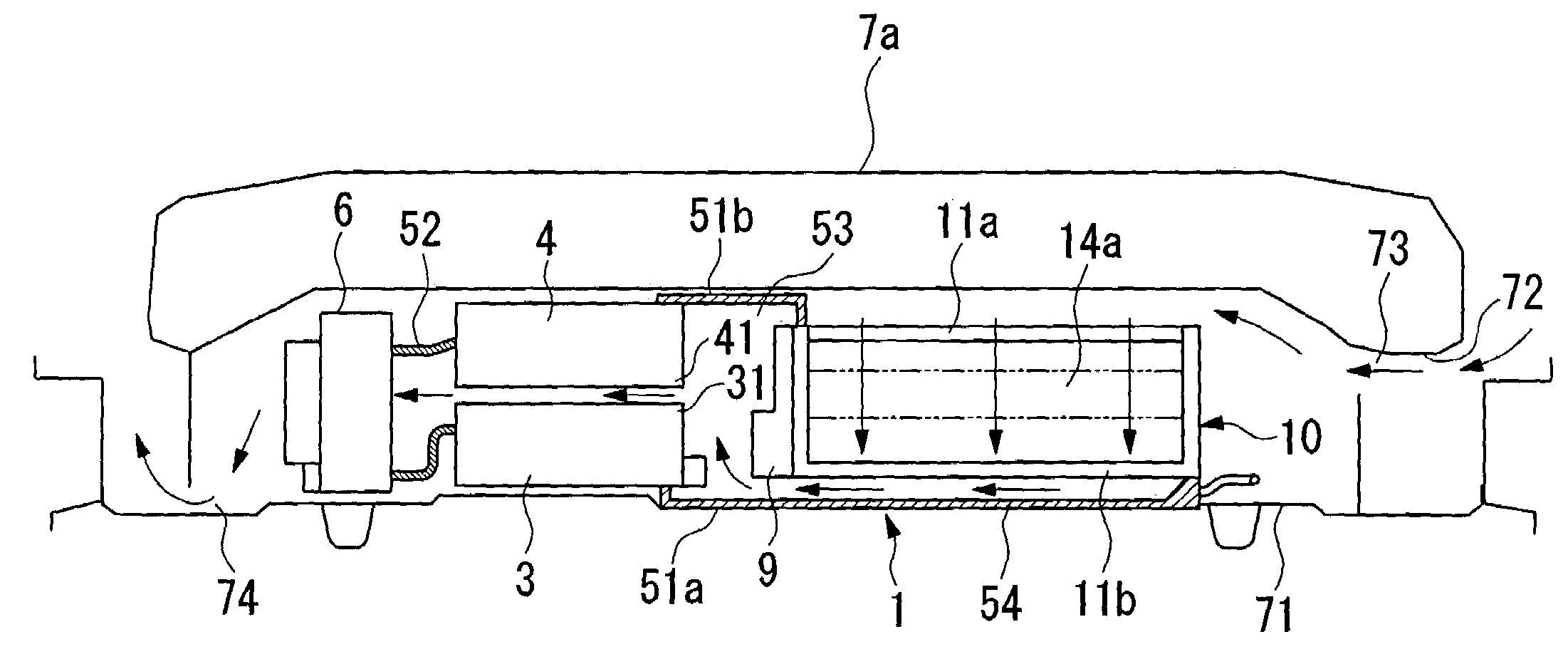
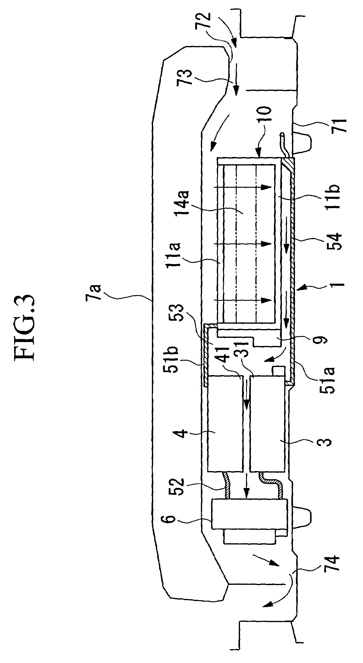
[0053]As shown in FIG. 1, a cooling device 1 for a high voltage electrical unit in this embodiment is installed under a rear seat 7 in such a manner that the longitudinal direction of the cooling device 1 coincides with a width direction of the vehicle. As shown in a schematic diagram in FIG. 2, the cooling device 1 includes a PDU 3 (an inverter) for controlling a motor 2 for driving the vehicle, a battery 10 (an electrical energy storing device) for supplying electrical energy to the motor 2 via the PDU 3, a DC / DC ...


PUM


Abstract

A cooling device for a high voltage electrical unit for a motor of a vehicle, includes: an inverter for controlling the motor that drives the vehicle; an electrical energy storing device for supplying electrical energy to the motor via the inverter; a downverter for decreasing source voltage of the electrical energy storing device, the downverter, the inverter, and the electrical energy storing device disposed under a seat of the vehicle in a concentrated manner; a fan, disposed under the seat, for moving cooling air to the electrical energy storing device and the inverter; an air inlet disposed under the seat and at an end of the seat as viewed in a width direction of the vehicle; and an air outlet disposed under the seat and at the other end of the seat as viewed in a width direction of the vehicle.

Description

BACKGROUND OF THE INVENTION[0001]1. Field of the Invention[0002]The present invention relates to a cooling device for a high voltage electrical unit for a motor of a vehicle, which is provided for cooling the high voltage electrical unit (including an electrical energy storing device, an inverter, etc.) installed in a vehicle which is solely driven by a motor, or in a vehicle which is driven by an engine and a motor. The present invention also relates to a hybrid vehicle having the cooling device for a high voltage electrical unit for a motor of a vehicle.[0003]Priority is claimed on Japanese Patent Applications Nos. 2003-395283, filed Nov. 26, 2003, and 2004-145239, filed May 14, 2004, the contents of which are incorporated herein by reference.[0004]2. Description of Related Art[0005]In a vehicle which is solely driven by a motor, or in a vehicle which is driven by an engine and a motor (hereinafter referred to as a hybrid vehicle), when electrical energy is supplied from a battery...

Claims


Application Information

Patent Timeline
Patent Type & Authority Patents(United States)
IPC IPC(8): H05K7/20B60K1/04B60K6/22B60K6/28B60K6/40B60K11/06B60K11/08B60L3/00B60L11/00H02B1/00H05K7/14
CPCB60L15/007H05K7/20909H01M10/5067H01M10/5016H01M10/5004B60H2001/003H01M10/613H01M10/625H01M10/6563Y02E60/10Y02T10/64
Inventor YAMAGUCHI, HIROOOHTSUKA, HIROSHIHASEGAWA, OSAMUMATSUOKA, TOSHIYUKIFUCHIBE, KOSHIROHASEGAWA, KUNIOSATO, HIROMITSU
Owner HONDA MOTOR CO LTD
Why Eureka
Try Eureka