Multi-screw extruder

a multi-screw, extruder technology, applied in the direction of mixing/kneading, manufacturing tools, food shaping, etc., can solve the problems of reducing the overall retention time of the product in such a process, reducing the investment cost of such an extruder, etc., to facilitate the conveying effect improve the conveying capacity of the screw elements, and increase the holding capacity of the ring extruder

Inactive Publication Date: 2006-07-25
BUHLER THERMAL PROCESSES
View PDF75 Cites 20 Cited by
  • Summary
  • Abstract
  • Description
  • Claims
  • Application Information

AI Technical Summary

Benefits of technology

[0012]The leading edge of the conveying screw elements preferably runs perpendicular to the axial direction of the extruder, at least at the radial edge area of the webs of the screw elements. This facilitates the conveying effect of the screw elements.
[0013]The trailing edge of the conveying screw elements also preferably runs perpendicular to the axial direction of the extruder, at least at the radial edge area of the webs. This also helps increase the holding capacity of the ring extruder according to the invention for loose bulk material like RPET flakes or RPET chips.
[0014]Other advantageous embodiments of the leading edge at the radial edge area of a web of conveying elements are characterized in that the leading edges run in the conveying direction overlapping the perpendicular to the axial direction, or that the leading edges are concave at least at the edge area of the webs. As an alternative or in addition, the leading edges (active edges) can also be back cut at the edge area of the webs. All of these measures also help improve the conveying capacity of screw elements designed in this way.
[0015]In a particularly advantageous embodiment of the invention, the axial partial area of the hollow space containing the screws located in the area of the feed hole is radially expanded, and this radial expansion extends along a portion of the screw rim in its circumferential direction. This step increases the process space volume in this axial partial area at the feed hole, which is particularly advantageous for the feed behavior of the extruder according to the invention for loose bulk material. In particular when preparing RPET, which is compacted and later melted when processed, this has a particularly advantageous effect.
[0016]The expansion here preferably extends along the circumference of the screw rim in the circumferential direction on either side away from the feed hole, and extends between the respective radially outer surface of the hollow space and the screw rim. This enables a particularly effective feeding of the ring extruder both in its outer process space via expansion along the circumference of the screw rim, as well as in its inner process space through the gap or gaps. A stuffing screw can be attached to the feed hole to increase the feed capacity. In addition, the extruder casing can still have vent holes in proximity to the feed hole, which are preferably exposed to a pressure below atmospheric pressure. This makes it possible to increase the feed capacity for loose bulk material even further for the extruder according to the invention.
[0017]In another preferred embodiment, at least one web is removed in the extruder according to the invention with at least one multi-threaded conveying element in the fill zone. One of the webs can be completely removed in a two-web conveying element, or even two of the three webs in a triple-threaded conveying element can be removed. It is sufficient for one of the webs to be present throughout for each conveying element, and interact with its adjacent conveying element in a tightly meshing and mutually stripping manner. The free space obtained by omitting the webs also has a positive effect on the feed behavior of the ring extruder according to the invention.

Problems solved by technology

The later are hence omitted entirely, which decreases the investment costs for such an extruder, and reduces the overall retention time of the product in such a process.
Another potential disadvantage of such “compensation zones” of prior art is that they lie in an area of the method used for other processing purposes, e.g., the melting zone.

Method used


Image

  • Multi-screw extruder
  • Multi-screw extruder
  • Multi-screw extruder

Examples


Embodiment Construction

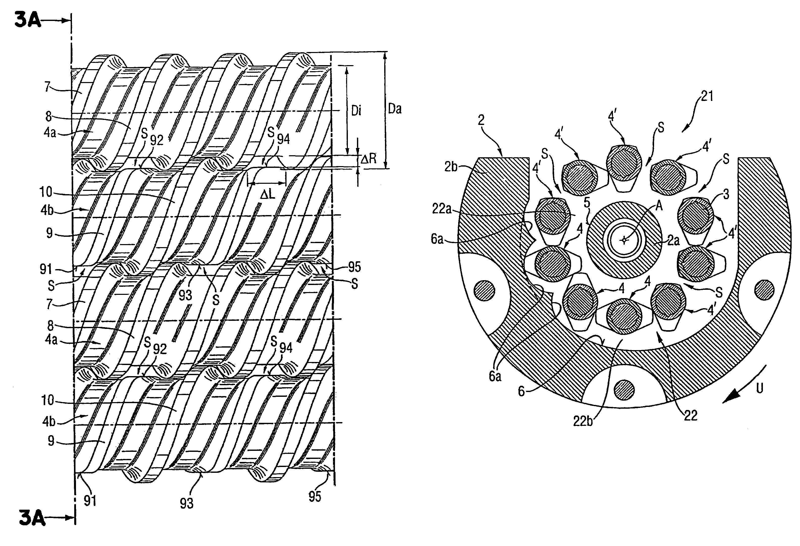
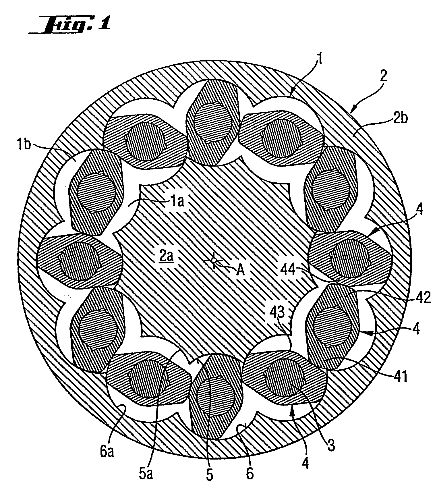
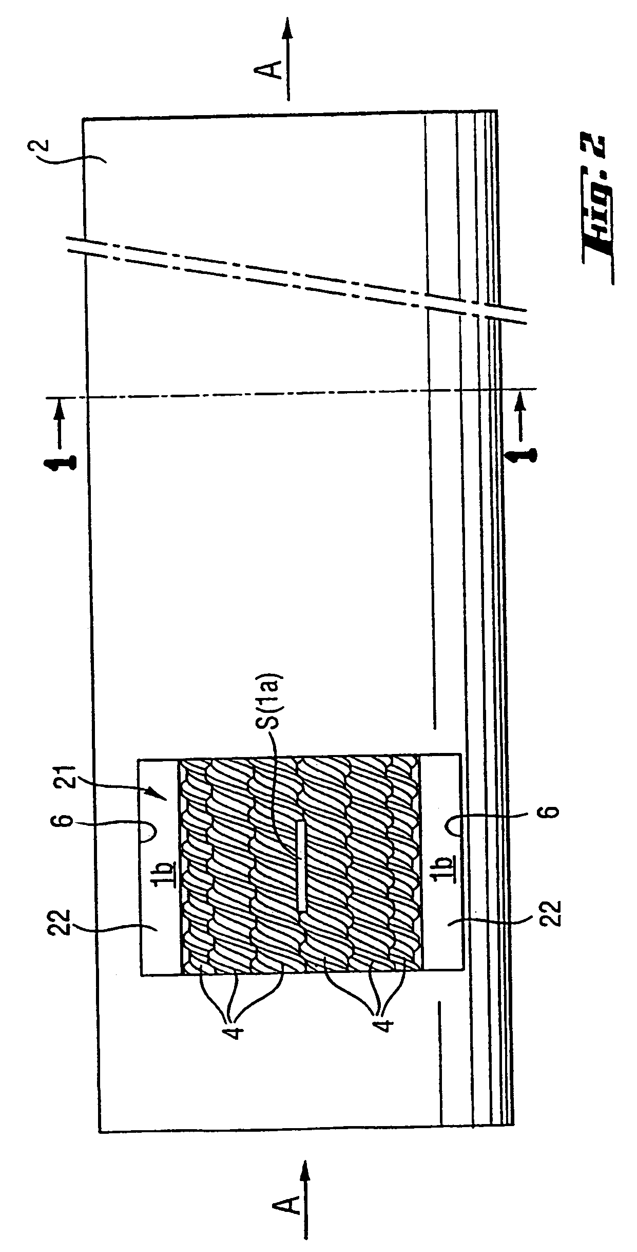
[0029]FIG. 1 is a partial section through a 12-screw ring extruder perpendicular to axial direction A along a sectional plane 1—1 (see FIG. 2). This sectional view describes both the section through a ring extruder according to prior art as well as through a ring extruder according to this invention. The extruder casing 2 consists of a core 2a and outer casing 2b. Extending between the core 2a and outer casing 2b is a rim-like hollow space 1, which is divided into an inner process space 1a and an outer process space 1b by screws 3 arranged in a rim in this hollow space 1, which each carry a processing element or conveying element 4. The processing elements 4 shown here are double-threaded conveying elements each with a first flight 41 and a second flight 42. The screw profile (along axial direction A) is preferably designed in such a way that adjacent conveying elements 4 always contact each other, so that the first web 41 and second web 42 of a conveying element 4 is in contact wit...


PUM

PropertyMeasurementUnit
outer diameter Daaaaaaaaaaa

Abstract

The invention relates to a multi-shaft extruder for the continuous treatment and/or processing of bulk material, especially a powdery, granular or flocculent product, comprising a plurality of shafts (3) which are arranged in a crown-like manner in a cavity (1) of an extruder housing (2), said shafts extending parallel to the axial direction (A) of the extruder and forming an inner processing chamber (1a) inside the crown, and an outer processing chamber (1b) outside the crown. Each shaft carries a number of axially successive processing elements (4), at least part of the same being elements (4a; 4c; 4e) having a transporting effect, and with which adjacent shafts engage in a sealed manner at least in partial regions. At least one transporting endless screw element (4b; 4d; 4f) comprising at least one transporting screw thread (9, 10; 14, 15, 16; 19, 20) is placed in the region of the supply opening (21) in the extruder housing (2), and does not engage in a sealing manner in at least one partial region along the axial direction (A).

Description

BACKGROUND OF THE INVENTION[0001]The invention relates to a multi-screw extruder for the continuous processing and / or working of a bulk material, in particular a powder, grain or flaked product, and to a method for filling the processing spaces of such a multi-screw extruder.[0002]Multi-screw extruders for processing and / or working bulk material are known in the art. A special group of multi-screw extruders has parallel abutting screws divided into a first process space and second process space for processing the product inside the extruders. In areas where the processing elements are tightly meshing conveying elements, there is essentially no connection to enable an exchange of material between the first process space and the second process space at least in this area. At most gases and traces of the most finely distributed product can get from one to the other process space. The impossibility of any product exchange between the two process spaces is particularly disadvantages in t...

Claims


Application Information

Patent Timeline
Patent Type & Authority Patents(United States)
IPC IPC(8): B29B7/48B29C47/42B29C48/43B29C48/50
CPCB29C47/42B29C47/625B29C47/60B29C47/585B29C47/0009B29C48/03B29C48/435B29C48/501B29C48/65B29C48/43B29B7/485
Inventor INNEREBNER, FEDERICOCHRISTEL, ANDREASSTURM, ACHIM-PHILIPPSCHWEIKLE, JURGEN
Owner BUHLER THERMAL PROCESSES
Why Eureka
Try Eureka