
Power system for a telecommunications facility

a technology for telecommunications facilities and power systems, applied in the direction of machines/engines, mechanical equipment, electrochemical generators, etc., can solve the problems of power systems for telecommunications facilities, components will eventually overheat and fail, and the operation of digital components generates a significant amount of hea

Active Publication Date: 2006-07-25
T MOBILE INNOVATIONS LLC
View PDF69 Cites 30 Cited by
  • Summary
  • Abstract
  • Description
  • Claims
  • Application Information

AI Technical Summary

Problems solved by technology

Under normal conditions, the operation of these digital components generates a significant amount of heat.
In fact, if they are not cooled, the components will eventually overheat and fail.
There are several disadvantages inherent in the typical power systems for telecommunications facilities.
For example, the cost of local electrical utility service has risen dramatically in recent years so that the cost of local electrical utility power is now a large component of a facility's overall power expenses.
Moreover, the increased number of digital components has caused the facility's power demands to increase.
In addition to being another factor that increases a facility's power expenses, the increased demand requires more batteries to provide an adequate amount of backup power for a reasonable period of time.
Clearly, the component cost of the system increases when more batteries are required.
Also, the greater number of batteries required has significantly increased the space required to house the system, which increases the spatial cost of the system.
Finally, it is known that generators suffer from certain reliability problems, such as failing to start when needed because of disuse or failed maintenance, so that the overall effectiveness of the system is less than desired.
There is yet another disadvantage with the conventional systems that relates to the air cooling system.
Unfortunately, current backup systems struggle to provide this amount of power in addition to satisfying the facility's power demands.
This situation may cause the air cooling system to perform at a diminished capacity when power is being supplied by a backup power source.
If the air cooling system does not perform at an optimal level, there is an increased risk that the facility's digital components will overheat and fail.
The power system employs redundant sources of power, and thus, is uninterruptible.

Method used


Image

  • Power system for a telecommunications facility
  • Power system for a telecommunications facility
  • Power system for a telecommunications facility

Examples


Embodiment Construction

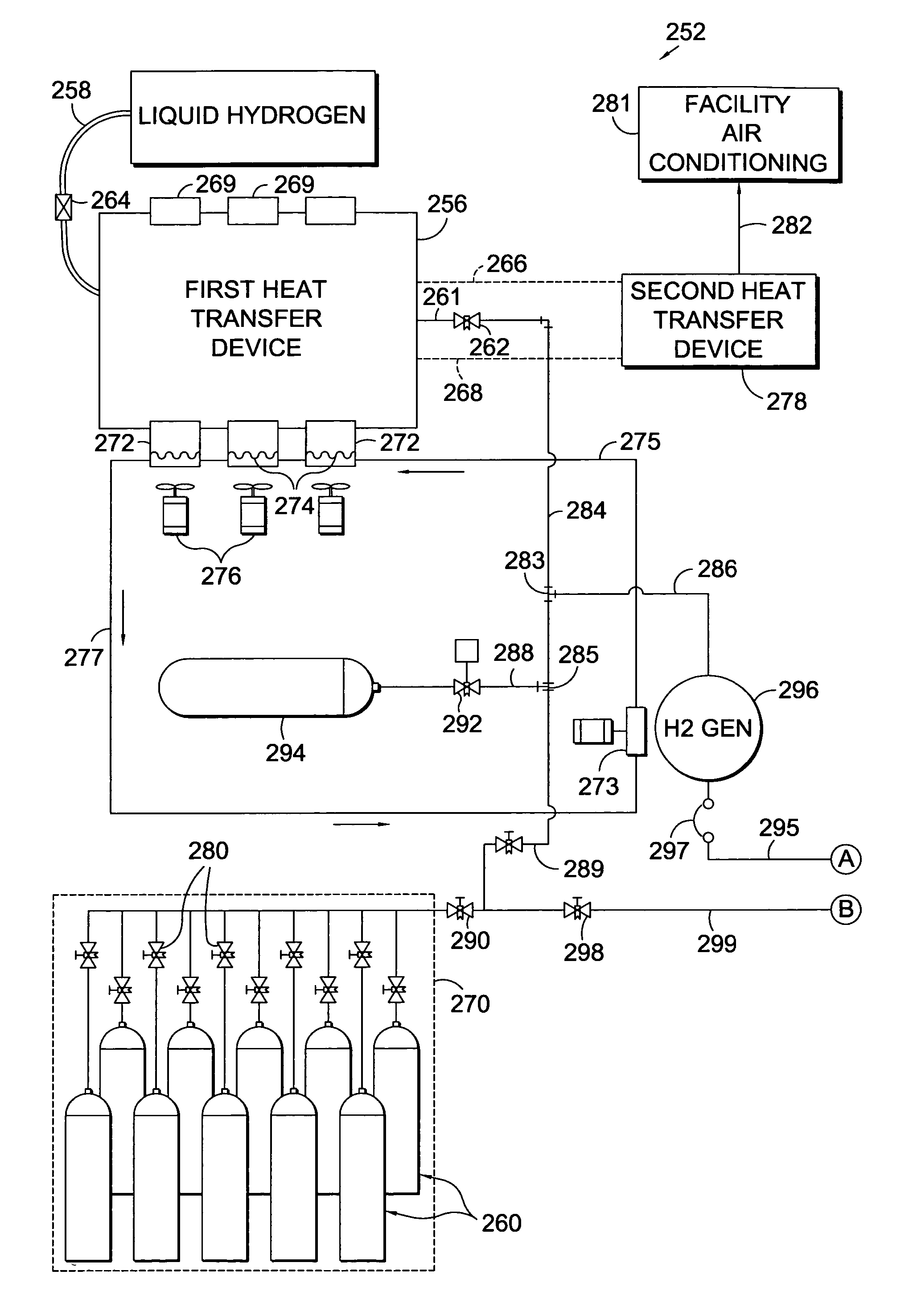
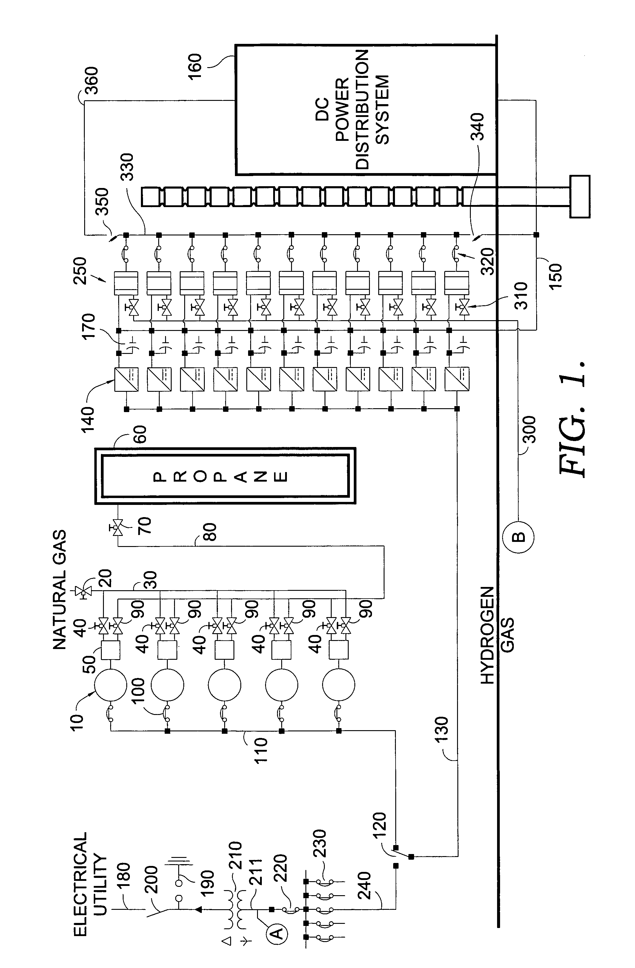
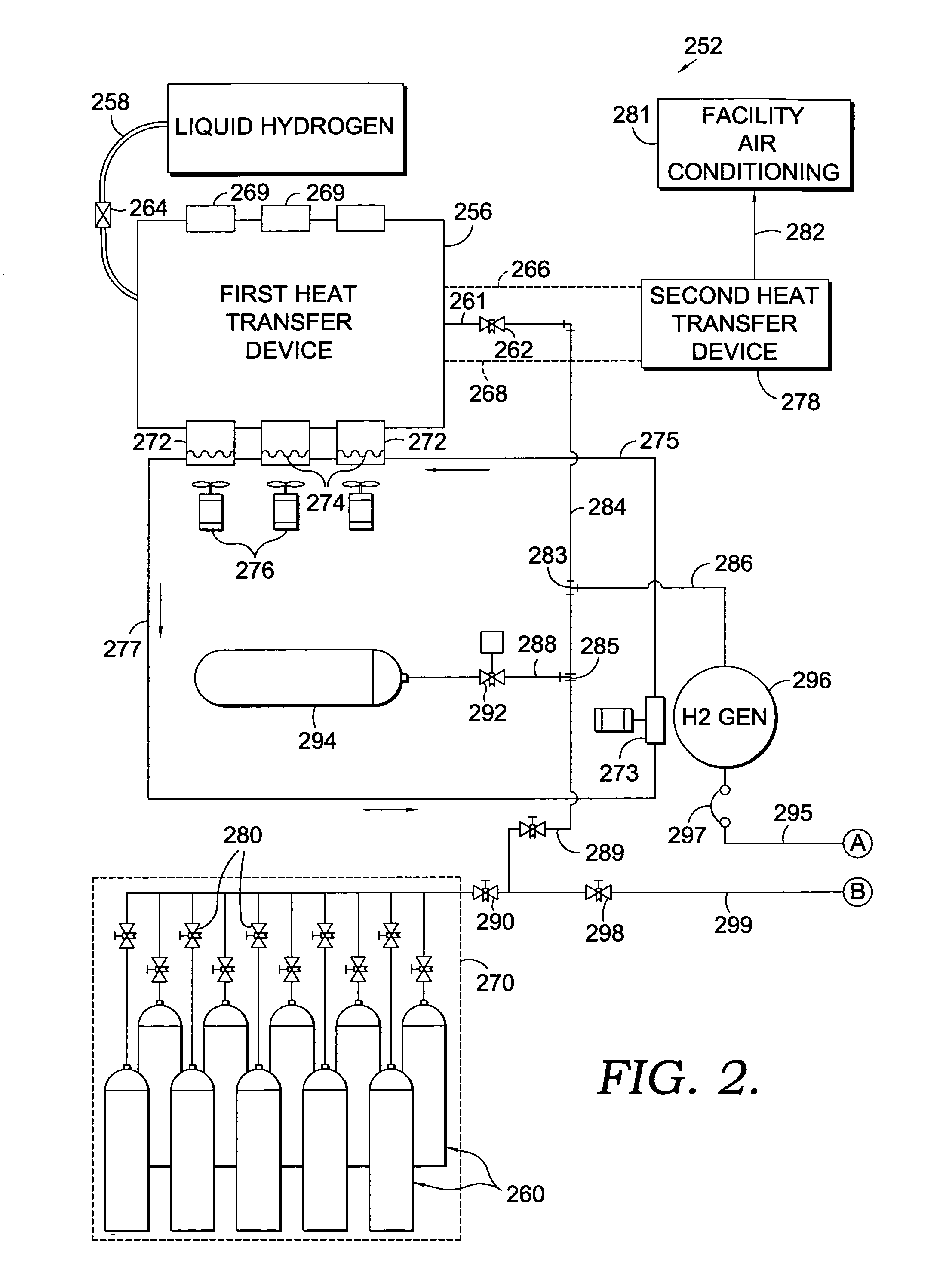
[0017]The present invention, in one embodiment, works along with a power system for a telecommunications facility. The novel power generation facility with which the present invention may be used employs liquid hydrogen as an energy source. In the embodied system, the hydrogen is used in two ways. It may be combusted, or it may be introduced into a battery of proton-exchange devices. For combustion, the system provides an internal combustion engine. This internal combustion engine is used to generate alternating current (AC) to satisfy the standard needs which are typical for all facilities, e.g., the heating, air conditioning, lighting, inter alia. The direct current (DC) generated by the introduction of hydrogen into the battery of proton exchange devices is used to meet the special DC power needs of the telecommunications facility, e.g., phone line support.

[0018]Before being used to generate energy for either method, the liquid hydrogen must first be converted to vapor. The vapor...


PUM

PropertyMeasurementUnit
electrical poweraaaaaaaaaa
poweraaaaaaaaaa
currentaaaaaaaaaa

Abstract

An energy generating system for a telecommunications facility includes a hydrogen fuel supply system. The hydrogen fuel supply system includes a source of liquid hydrogen which uses a high pressure expansion tank along with additional storage tanks. The system also incorporates first and second stage heat exchangers. The first stage exchanger is used to benefit from the endothermic reaction created when liquid hydrogen transforms into vapor. The cooling provided from this state change is transferred into a second medium which is delivered into a second stage heat transfer device and then used for air conditioning purposes. The system also includes a hydrogen generator which may be used to create AC power by combusting vaporous hydrogen.

Description

CROSS-REFERENCE TO RELATED APPLICATIONS[0001]None.STATEMENT REGARDING FEDERALLY SPONSORED RESEARCH OR DEVELOPMENT[0002]None.FIELD OF THE INVENTION[0003]In general, this invention provides a power system for a facility. More specifically, this invention provides a hydrogen-fueled backup system for immediate AC and DC power generation. The hydrogen fuel supply system, which converts liquid hydrogen to gas, is also used for cooling purposes in the facility.BACKGROUND OF THE INVENTION[0004]Digital electronic components make up a substantial part of the core technology of most modem telecommunications facilities. Under normal conditions, the operation of these digital components generates a significant amount of heat. In fact, if they are not cooled, the components will eventually overheat and fail. Thus, an operational air cooling system is critical to the continued optimal performance of the facility.[0005]Air cooling systems require electrical power for their operation. Traditionally,...

Claims


Application Information

Patent Timeline
Patent Type & Authority Patents(United States)
IPC IPC(8): H01M8/00
CPCB01B1/005F02B43/10F02D29/06F02D19/023F02M21/0206F02M21/0224F02M21/0287F02M21/06F02B3/06Y02T10/32Y02T10/30
Inventor JOHNSON, LARRY L.
Owner T MOBILE INNOVATIONS LLC
Learn More