Microscope for reflected-light and transmitted-light microscopy

a microscope and light transmission technology, applied in the field of microscopes, can solve the problems of alignment errors, poor contrast, and relatively weak lighting of objects to be observed, and achieve the effect of high resolution

Inactive Publication Date: 2006-07-25
CARL ZEISS MICROSCOPY GMBH
View PDF7 Cites 9 Cited by
  • Summary
  • Abstract
  • Description
  • Claims
  • Application Information

AI Technical Summary

Benefits of technology

[0011]On this basis, it is the primary object of the invention to increase efficiency in reflection and to ensure that the transmitted incident light is reflected back in itself again with high accuracy by the reflecting device.
[0016]Accordingly, in contrast to the conventional mirror, the distortion of the wavefront is corrected, as a result of which the light is imaged through the second objective again exactly in the focus of the microscope objective. Compensation of losses which still occur in the prior art due to imaging errors and alignment inaccuracies is substantially improved in this way.
[0017]When a laser source is used for illumination in connection with the construction according to the invention, nonlinear phenomena can be utilized very favorably because the probability of multiphoton absorption is substantially increased due to the bundling of the laser light when passing through the specimen two times. When the laser light is coupled into the microscope beam path via a dichroic beam splitter, the doubled wavelength which is diffusely reflected by the specimen can be observed in a simple manner.
[0019]With an arrangement of this type, the two objectives which are located opposite one another symmetrically with respect to the specimen with homogeneous immersion advantageously form an optical resonator by which very small phase interferences introduced in the resonator by the specimen can be detected and can accordingly provide information about the specimen with high resolution.

Problems solved by technology

However, because of the influence of image errors (aberrations, etc.) and alignment or adjustment inaccuracies, the image of the object to be observed has relatively weak lighting and poor contrast.
However, the reflection carried out in this manner also has alignment inaccuracies and image errors, as a result of which the light is not exactly parallel after the second objective or the object to be observed is not imaged onto itself with lateral and vertical precision.

Method used


Image

  • Microscope for reflected-light and transmitted-light microscopy
  • Microscope for reflected-light and transmitted-light microscopy
  • Microscope for reflected-light and transmitted-light microscopy

Examples


Embodiment Construction

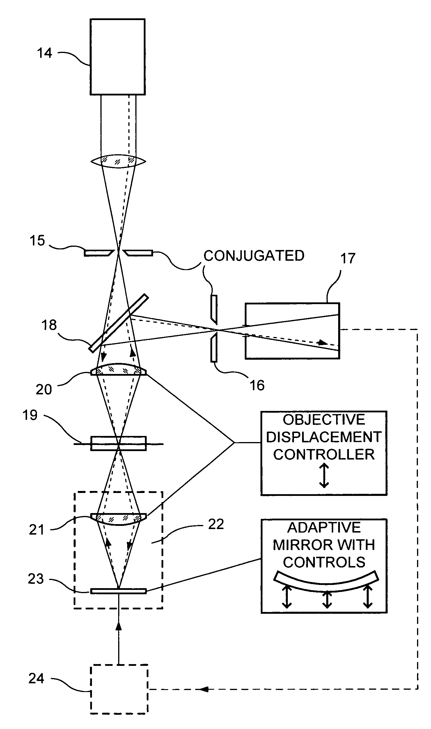
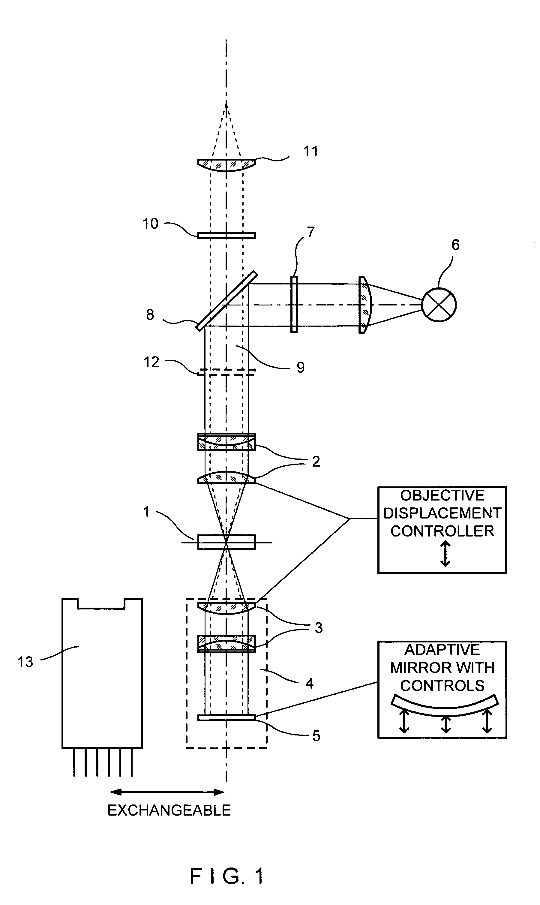
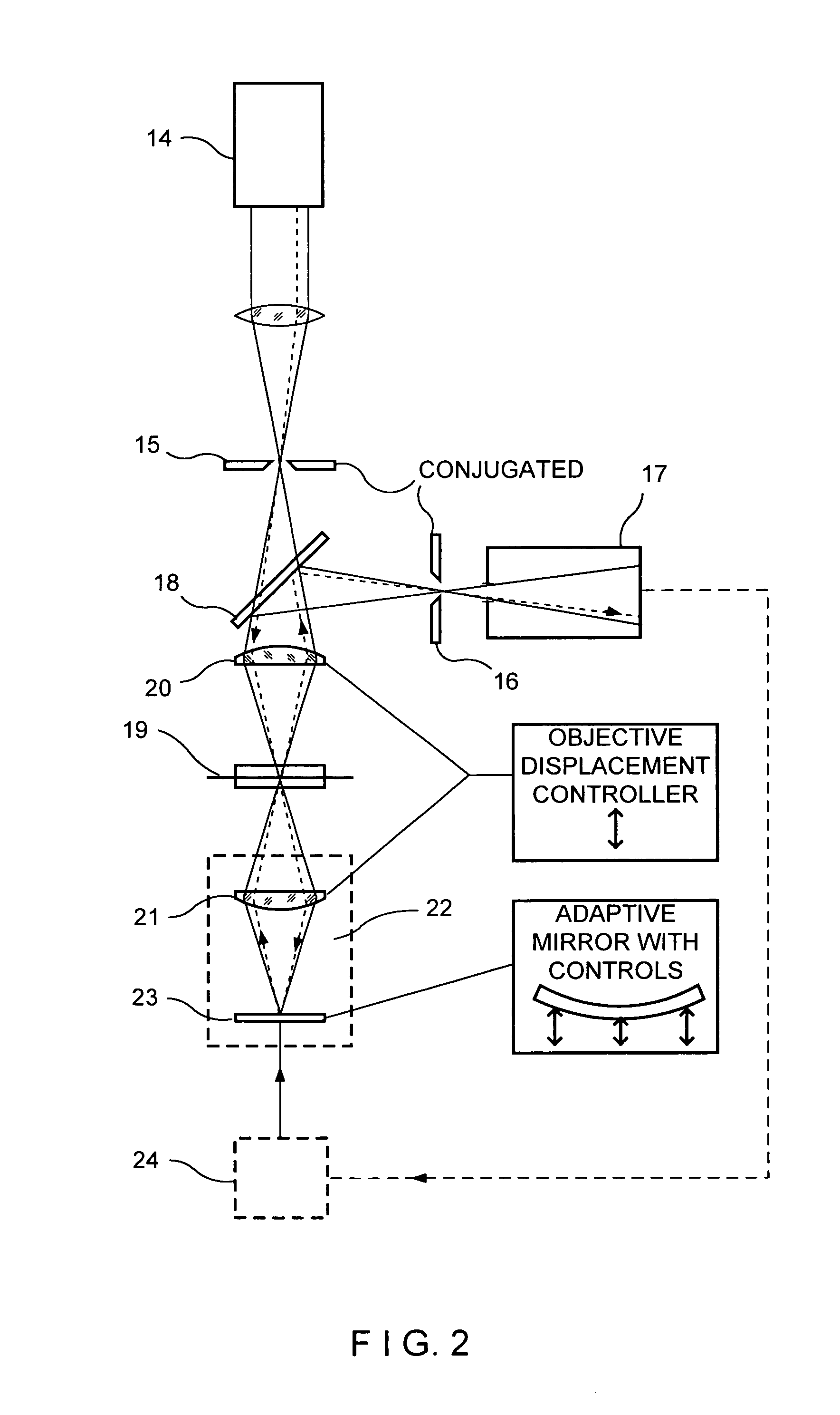
[0023]In FIG. 1, a specimen 1 is received between the microscope objective 2 and another objective 3 which is identical to the microscope objective 2 with respect to its optical characteristics and which is part of a reflecting device 4. Optimum resolutions result when, for example, planaprochromats with a numerical aperture greater than or equal to 1.4 are used for both objectives 2, 3.

[0024]It is further advantageous when the preparation is received between two identical, high-grade cover glasses which ensure a perfectly symmetrical beam path.

[0025]A mirror 5 which reflects the light transmitted through the specimen 1 back into itself exactly is arranged in the reflecting device 4 following the objective 3. The reflecting surface of the mirror 5 is not plane, but rather has a sphere which is adapted to the wavefront of the objective 3 to a first approximation. In a particularly preferred manner, the mirror surface is curved aspherically and adapted to the output wavefront of the o...


PUM


Abstract

A microscope is disclosed in which a specimen is arranged between two objectives and can be observed with reflected light as well as with transmitted light. In a microscope with field transmission, two objectives have substantially identical optical characteristics and at least one of the two objectives is followed by a mirror which reflects the light transmitted through the specimen back into itself exactly. In this way, there is twofold transmission through the specimen with optimum illumination of the solid angle. In a laser scanning microscope, there are likewise two objectives with identical optical characteristics and at least one of the objectives is followed by a phase-conjugating or adaptive mirror.

Description

[0001]This is a continuation application of parent U.S. patent application Ser. No. 09 / 658,321 filed Sep. 8, 2000, now abandoned which claims priority of DE 199 42 998.7 filed Sep. 9, 1999, all of which are incorporated herein by reference.BACKGROUND OF THE INVENTION[0002]1. Field of the Invention[0003]The invention is directed to a microscope in which a specimen is arranged between two objectives and can be observed with reflected light as well as with transmitted light.[0004]2. Description of the Related Art[0005]An important concern in further developments in microscopy at present is to provide and perfect methods and arrangements which make it possible to observe objects by twofold transmission with reflected light as well as with transmitted light, which serves to increase both resolving capacity and contrast.[0006]In this regard, there are already known arrangements in which incident light transmitted by the object is reflected back to the rear of the object again by a reflect...

Claims


Application Information

Patent Timeline
Patent Type & Authority Patents(United States)
IPC IPC(8): G02B21/06G02B21/00G02B21/16G02B21/02G02B21/04G02B21/08
CPCG02B21/088
Inventor MUELLER, GERHARD J.WOLLESCHENSKY, RALF
Owner CARL ZEISS MICROSCOPY GMBH
Why Eureka
Try Eureka