
Network communication system with relay node for broadcasts and multicasts
a network communication system and relay node technology, applied in data switching networks, special service provisioning for substations, digital transmission, etc., can solve the problems of difficult routing, large network traffic, and high user data copying requirements, and achieve automatic avoidance of looped paths, simplify routing, and simplify the effect of information routing
- Summary
- Abstract
- Description
- Claims
- Application Information
AI Technical Summary
Benefits of technology
Problems solved by technology
Method used
Image

Examples
first embodiment
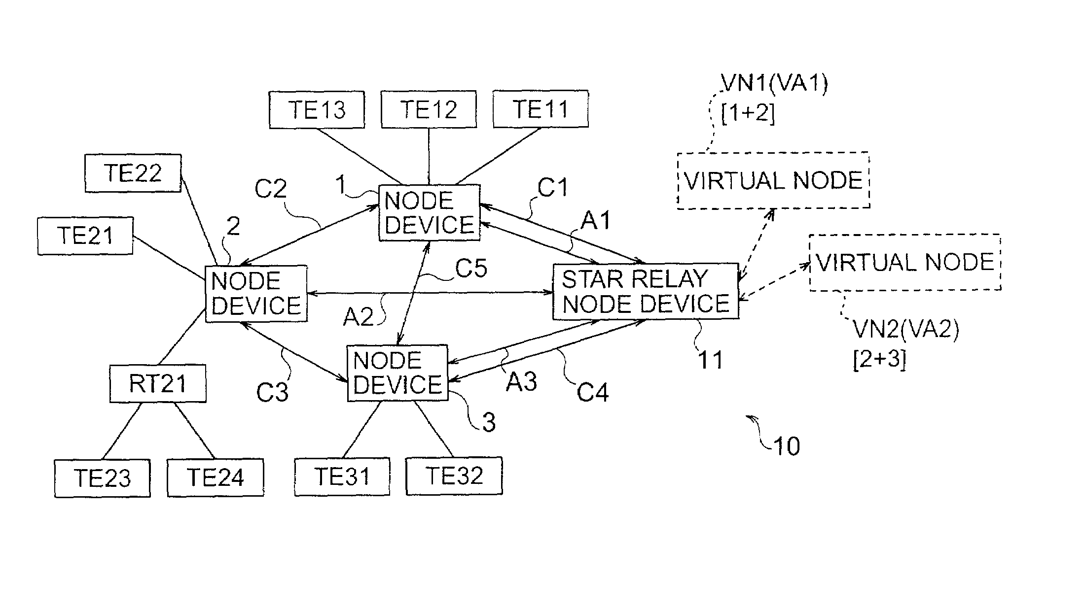
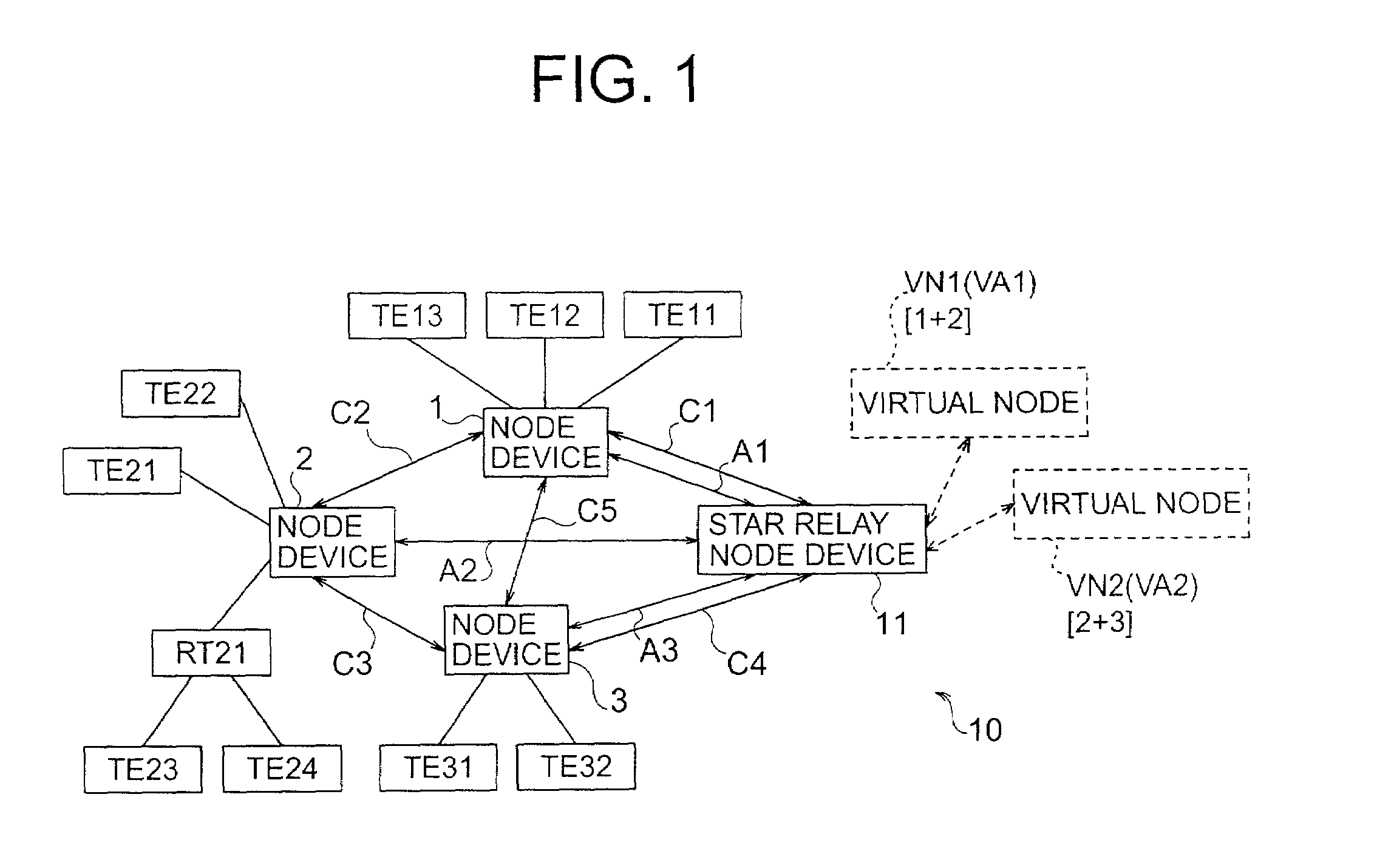
[0037]FIG. 1 shows an example of the general structure of a network communication system 10 embodying the present invention. The network communication system 10 in FIG. 1 includes node devices 1, 2, 3 and a star relay node device 11.
[0038]The node devices 1 to 3 may be terminal devices such as personal computers having networking functions, but in the present embodiment the node devices will be assumed to be routers that provide service to personal computers or other terminal equipment. Specifically, node device 1 (a router) serves terminals TE11 to TE13, node device 2 (another router) serves terminals TE21 to TE24, and node device 3 (another router) serves terminals TE31 and TE32. Terminals TE23 and TE24 are connected to node device 2 through yet another router RT21 instead of being connected to node device 2 directly. Router RT21 and terminals TE23, TE24 form a type of local area network (LAN), which may also include node device 2. Similarly, node device 1 and terminals TE11 to TE...
second embodiment
[0088]The second embodiment will be described below only insofar as it differs from the first embodiment. The difference between the two embodiments is that the second embodiment uses optical communication lines and wavelength division multiplexing (WDM).
[0089]FIG. 5 shows an example of the overall structure of a network communication system 30 according to the second embodiment. The network communication system 30 comprises node devices 1A, 2A, 3A and a star relay node device 11A. Elements in FIG. 5 indicated by the same reference characters as in FIG. 1, or by similar reference characters, have corresponding functions. Specifically, the functions of virtual nodes VN1 and VN2 are the same as in FIG. 1, node devices 1A, 2A, 3A correspond to node devices 1, 2, 3 in FIG. 1, star relay node device 11A corresponds to star relay node device 11 in FIG. 1, and lines CC1, CC2, CC3, CC4, CC5 correspond to lines C1, C2, C3, C4, C5 in FIG. 1. Lines CO1, CO2, CO3 correspond to lines A1, A2, A3 ...
third embodiment
[0100]The third embodiment will be described below only insofar as it differs from the first embodiment. The difference is that the third embodiment dispenses with virtual nodes (and virtual addresses), and has the node device that requests a multicast perform source routing. Source routing allows the sending (source) node to designate paths under the internet protocol described in the document Request for Comments 791.
[0101]FIG. 8 shows an example of the overall structure of a network communication system 40 according to the third embodiment. FIG. 9 shows an example of the structure of the main parts of the star relay node device 11C in the third embodiment; FIG. 10 shows an example of the structure of the main parts of node devices 1C to 3C. Signals and other elements in FIGS. 9 and 10 indicated by the same reference characters as in FIGS. 2 and 3 have corresponding functions.
[0102]The node devices in the third embodiment will now be described with reference to FIG. 10. It will be...
PUM
 Abstract
Description
Claims
Application Information