
Multiple core microstructured optical fibers and methods using said fibers

a microstructured, optical fiber technology, applied in the field of optical fibers, can solve the problems of destroying the light-guiding properties of the fiber, unable to use standard methods of measuring fiber properties, and difficult to perform diagnostic measurements on hollow core photonic band gap fibers, etc., to simplify the initial steps of the active alignment process

Active Publication Date: 2006-07-25
CORNING INC
View PDF11 Cites 32 Cited by
  • Summary
  • Abstract
  • Description
  • Claims
  • Application Information

AI Technical Summary

Benefits of technology

[0015]The methods and optical fibers of the present invention result in a number of advantages over prior art microstructured optical fibers and methods. For example, the photonic band gap-guided core or the main core may be designed for a particular end use (e.g. telecommunications, data transfer, energy conduction) of the fiber, while a monitoring, splicing, or diagnostic function can be enabled by the at least one index-guided core or the at least one alignment core. The index-guided core or the alignment core can be designed to guide a different wavelength than the photonic band gap-guided core or the main core. The index-guided core or the alignment core may have a much larger area than the photonic band gap-guided core or the main core, simplifying the initial steps of an active alignment process. In splicing the microstructured optical fibers of the present invention, the propagating modes of the main core or photonic band gap-guided cores can be rotationally aligned by active alignment of the index-guided cores or the alignment cores. The microstructured optical fibers of the present invention enable the use of optical time domain reflectometry and visible light scattering techniques in diagnostic measurements of hollow-core photonic band gap fibers.

Problems solved by technology

A slight change in the photonic band gap structure may perturb its properties such that a light propagating in the core is no longer forbidden to propagate in the photonic band gap structure, destroying the light-guiding properties of the fiber.
It is difficult to perform diagnostic measurements on hollow core photonic band gap fibers.
If a fiber does not guide light, it may be due to a break in the fiber, or due to a shift of the band gap caused by a deviance from the desired fiber structure.
If the fiber does not guide light, standard methods of measuring fiber properties cannot be used.

Method used


Image

  • Multiple core microstructured optical fibers and methods using said fibers
  • Multiple core microstructured optical fibers and methods using said fibers
  • Multiple core microstructured optical fibers and methods using said fibers

Examples


Embodiment Construction

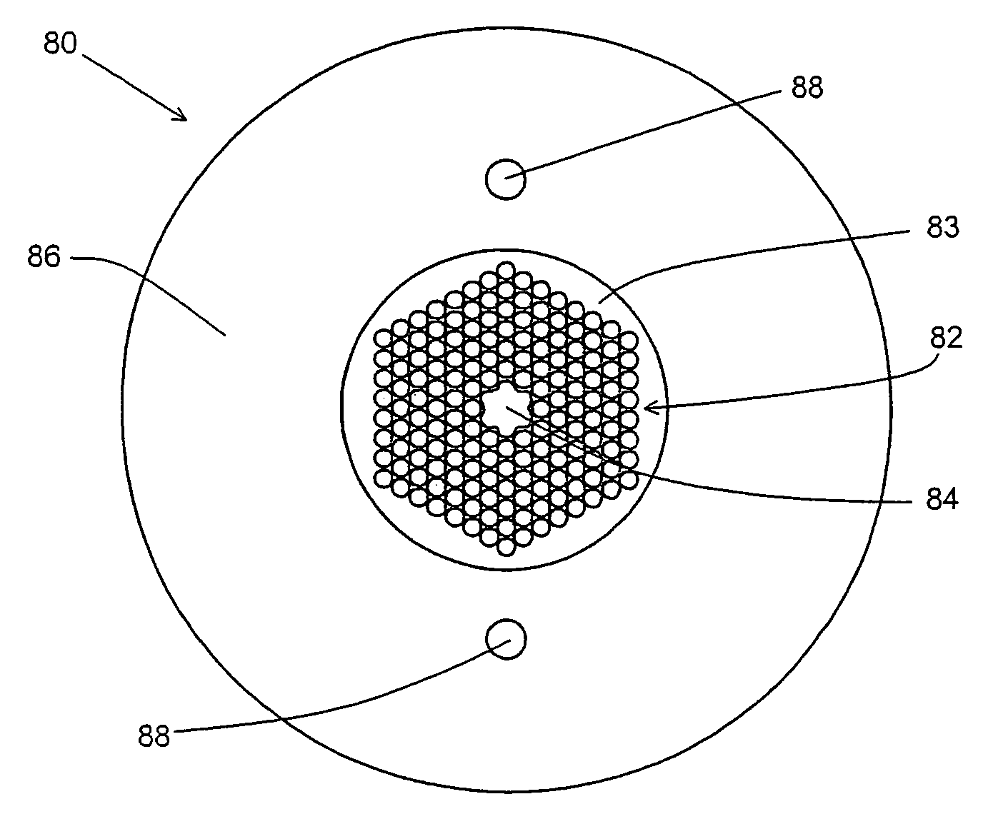
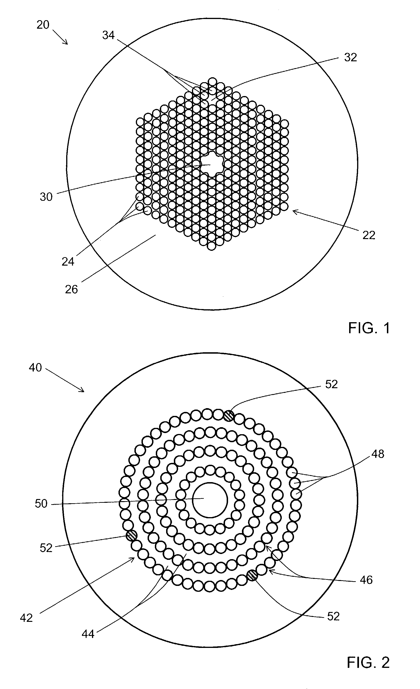
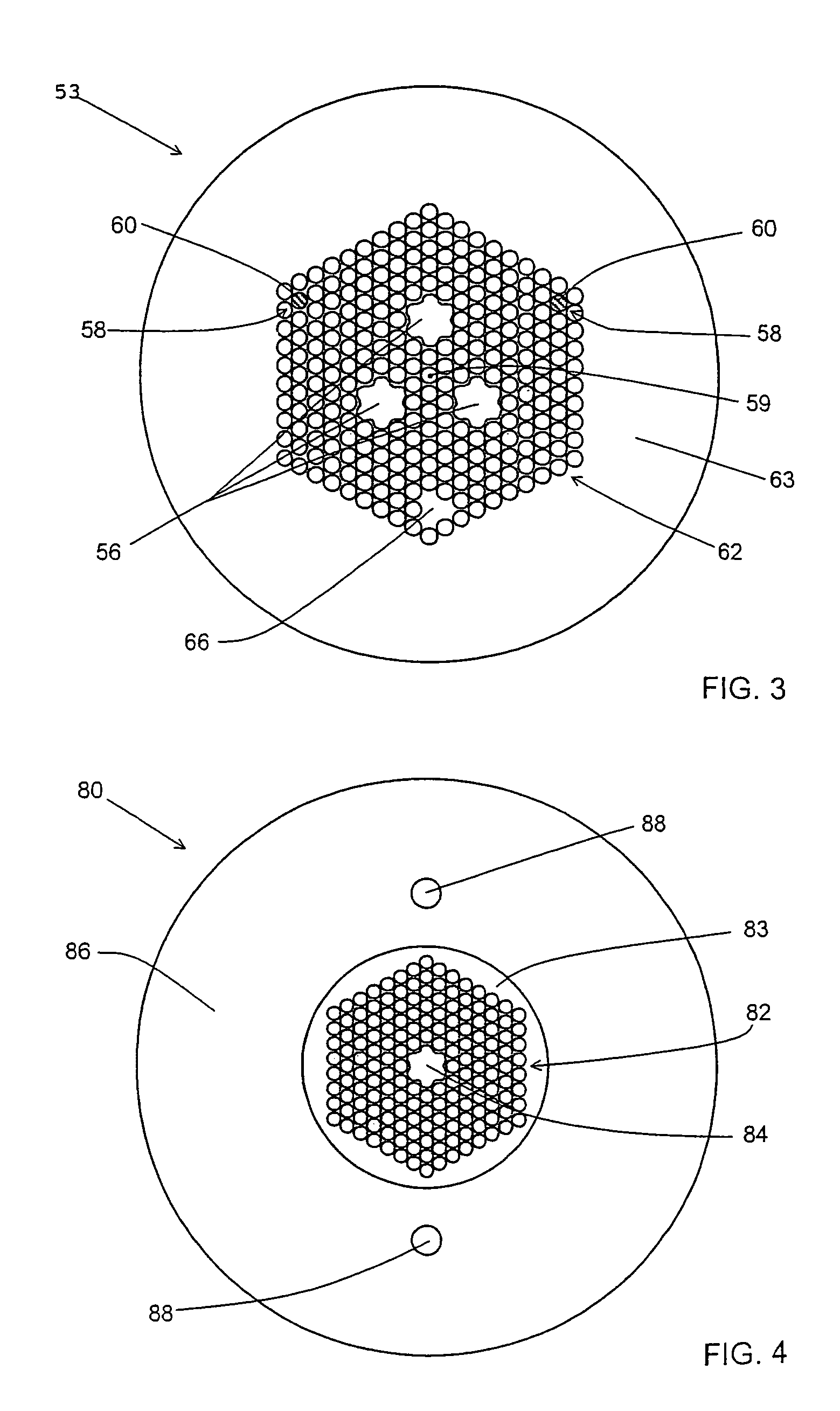
[0031]The present invention relates to a microstructured optical fiber having a photonic band gap-guided core; and at least one index-guided core. An example of a microstructured optical fiber according to one embodiment of the invention is shown in cross-sectional view in FIG. 1. Microstructured optical fiber 20 includes a photonic band gap structure 22 formed as a periodic array of holes 24 formed in matrix material 26 of the fiber. Photonic band gap structure 22 has a set of frequencies and propagation constants for which propagation through the band gap structure is essentially forbidden. This set of frequencies and propagation constants is known as the band gap of the photonic band gap structure. Photonic band gap-guided core 30 is provided as a large air-filled hole at the center of the fiber, and is surrounded by photonic band gap structure 22. As used herein, a photonic band gap-guided core is a structure that supports a propagating mode having a frequency and propagation co...


PUM

PropertyMeasurementUnit
Band gapaaaaaaaaaa
Microstructureaaaaaaaaaa
Distanceaaaaaaaaaa

Abstract

The present invention relates to a microstructured optical fiber including a photonic band gap-guided core; and at least one index-guided core. Another embodiment of the present invention relates to a microstructured optical fiber including a set of main cores; a microstructured region surrounding the set of main cores; and at least alignment core, the alignment cores having substantially different optical propagation properties than the main cores. The present invention also includes methods for coupling, monitoring, and locating discontinuities in the fibers of the present invention.

Description

BACKGROUND OF THE INVENTION[0001]1. Field of the Invention[0002]The present invention relates generally to optical fibers, and more specifically to microstructured optical fibers, methods for locating discontinuities in microstructured optical fibers, methods for monitoring the draw of microstructured optical fibers, and methods for coupling microstructured optical fibers.[0003]2. Technical Background[0004]Optical fibers formed completely from glass materials have been in commercial use for more than two decades. Although such optical fibers have represented a leap forward in the field of telecommunications, work on alternative optical fiber designs continues. One promising type of alternative optical fiber is a microstructured optical fiber, which includes holes or voids running longitudinally along the fiber axis. The holes generally contain air or an inert gas, but may also contain other materials.[0005]Microstructured optical fibers may be designed to have a wide variety of prop...

Claims


Application Information

Patent Timeline
IPC IPC(8): G02B6/02G02B6/255
CPCG02B6/02323G02B6/02333G02B6/02338G02B6/02347G02B6/02357G02B6/0238C03B37/0253C03B37/02781G02B6/02361C03B2203/42C03B2203/14C03B2203/34
Inventor FAJARDO, JAMES C.GALLAGHER, MICHAEL T.WEST, JAMES A.
Owner CORNING INC
Learn More