Surface-shaped light irradiation device

Active Publication Date: 2006-08-01
INTERDIGITAL CE PATENT HLDG
View PDF21 Cites 39 Cited by
  • Summary
  • Abstract
  • Description
  • Claims
  • Application Information

AI Technical Summary

Benefits of technology

[0012]In the surface-shaped light irradiation device of the present invention, it is preferred that the dot light source comprise a flat light emitting surface for emitting a light toward a part of an external surface, and be retained by the retaining section in a state where the light emitting surface abuts on the light entrance end surface of the light guiding plate. Due to this, it is possible to retain the set position of the dot light source more stably, and to more improve the intensity of the irradiation light by efficiently utilizing the emitted light without any loss. Further, it is preferred that the dot light source be fixed inside the retaining section by an adhesive agent stuffed between its surface other than the light emitting surface and the retaining section, the retaining section comprise a wall which is formed in such a manner as to protrud

Problems solved by technology

Since there are differences in thermal expansion coefficient and shrinkage ratio among the components constituting the surface-shaped light irradiation device using the dot light source, repetition of heating and cooling of this light irradiation device due to changes in atmospheric tempera

Method used


Image

  • Surface-shaped light irradiation device
  • Surface-shaped light irradiation device
  • Surface-shaped light irradiation device

Examples


Embodiment Construction

[0020]An embodiment of the present invention will now be specifically explained with reference to the drawings.

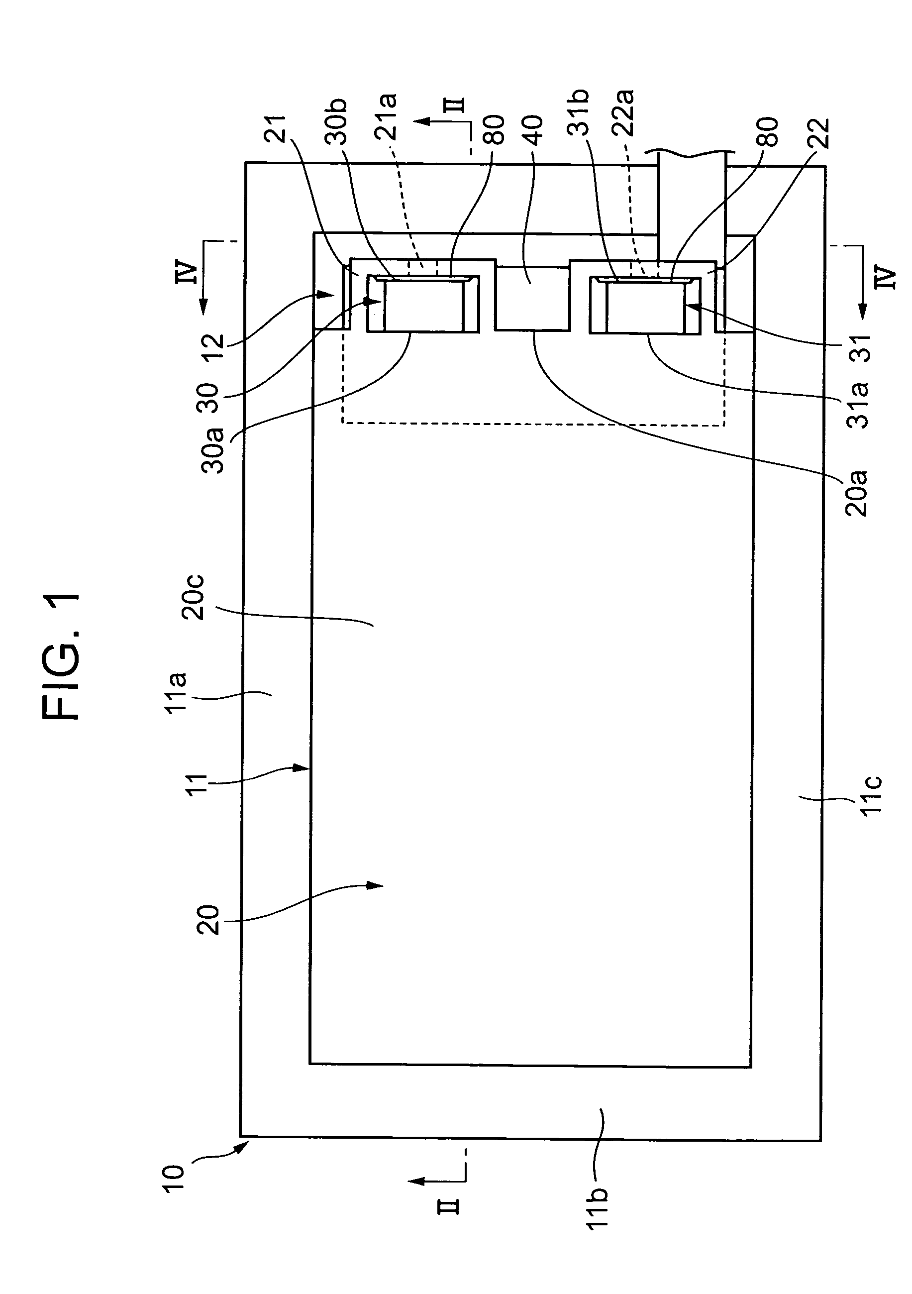
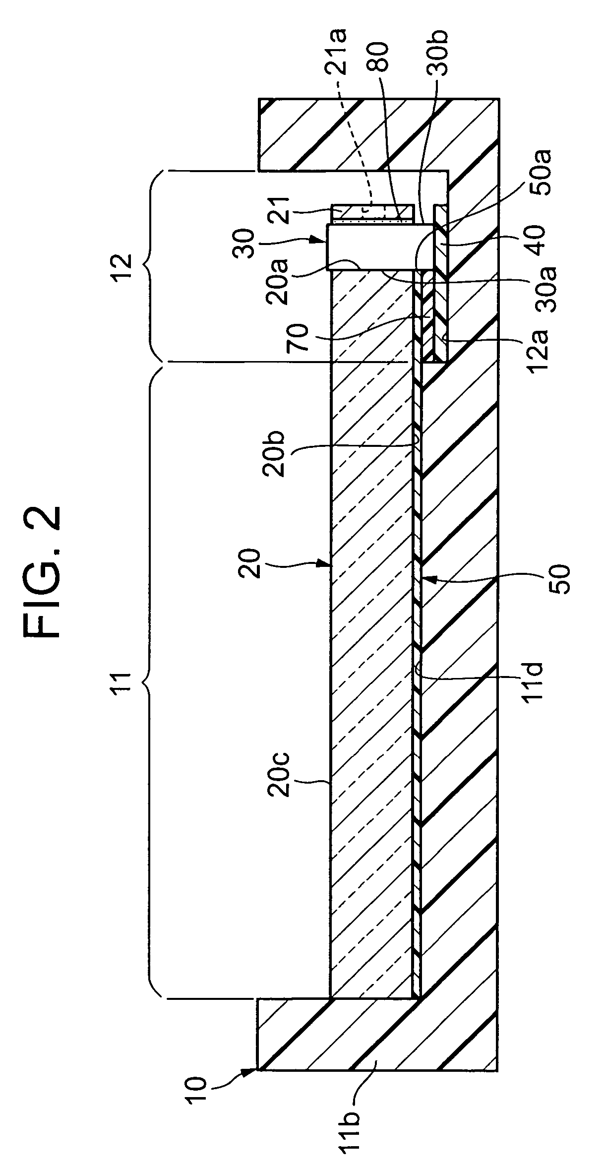
[0021]A backlight device for a liquid crystal display element as one embodiment of the present invention will be explained based on FIG. 1 to FIG. 4.

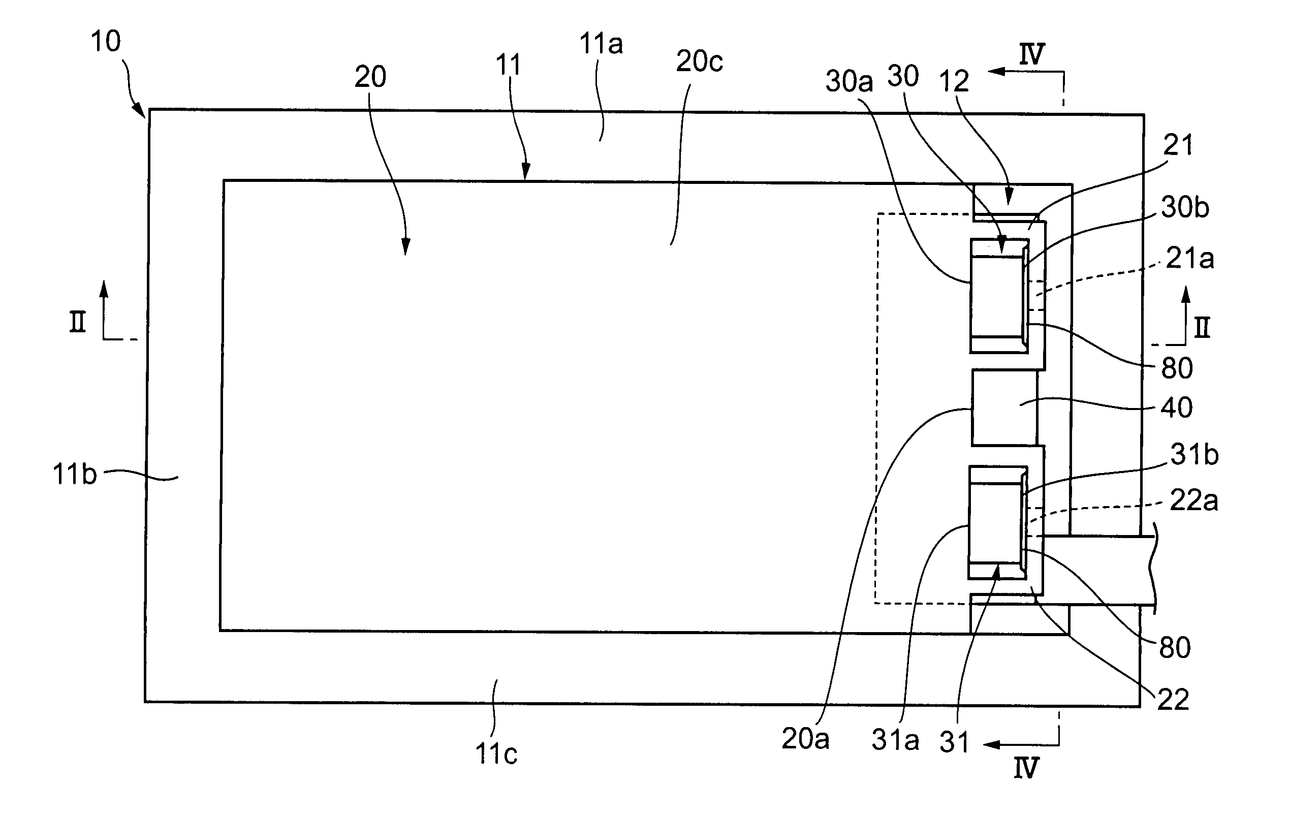
[0022]FIG. 1 is a top view showing a state where a backlight device according to the present embodiment is contained in a containing case 10. The containing case 10, whose appearance viewed from the top (hereinafter referred to as top view appearance) forms a rectangle, comprises a light guiding plate containing region 11 whose three sides are surrounded by side walls 11a to 11c, and a light source unit containing region 12 in which a light source and its accompanying circuit substrate, etc. i.e. the light source function of the present backlight device are / is contained.

[0023]A light guiding plate 20 made of a transparent material such as acryl resin or the like is contained in the light guiding plate containing region 11. The ...


PUM


Abstract

An LED is mounted on a flexible wiring board, and this flexible wiring board is adhered by a both-surface adhesive tape to a back of a light guiding plate to which a light reflecting film is adhered by an adhesive layer. The LED is kept at a desired set position by retaining the LED by a retaining section formed integrally with the light guiding plate in a state where a light emitting surface of the LED air tightly contacts a light entrance end surface of the light guiding plate, and by adhering a rear surface of the LED to an inner surface of the retaining section by an adhesive agent.

Description

BACKGROUND OF THE INVENTION[0001]1. Field of the Invention[0002]The present invention relates to a surface-shaped light irradiation device of a side light type which uses a dot light source.[0003]2. Description of the Related Art[0004]Conventionally, for the purpose of backlighting a liquid crystal display element, a light source is arranged in front of one end surface of a rectangular light guiding plate, and light emitted from this light source is introduced into this light guiding plate so as to be emitted from one plate surface of this light guiding plate. A surface-shaped light irradiation device of a side light type is widely used, which illuminates the liquid crystal display element with this light guiding plate oppositely arranged at the back of the liquid crystal display element. As a light source of this type of illumination device (light irradiation device), a dot light source such as a light emitting diode (hereinafter referred to as LED) or the like is employed in order...

Claims


Application Information

Patent Timeline
IPC IPC(8): F21V7/04F21V8/00G02F1/13357F21Y101/02
CPCG02B6/0055G02B6/0021
Inventor HIGASHIYAMA, HIROSHI
Owner INTERDIGITAL CE PATENT HLDG
Why Eureka
Try Eureka