Socket for electronic part

a technology for electronic parts and sockets, applied in the direction of coupling contact members, fixed connections, coupling device connections, etc., can solve the problems of difficult workability and assembly of contacts, comparatively high cost, and unsatisfactory connector boards, so as to increase the length of leaf spring electrode members, sharp enhancement of workability and assembly of electrode members

Inactive Publication Date: 2006-08-01
TNG CORP LTD
View PDF7 Cites 9 Cited by
  • Summary
  • Abstract
  • Description
  • Claims
  • Application Information

AI Technical Summary

Benefits of technology

[0010]The present invention has been made in order to eliminate such difficulties, and it has for its object provision of a connector board for electrically connecting electrode terminals of an electronic component with a printed circuit board which facilitates the assembly of the electrode terminals, which provides a stable contact resistance, which allows reduction in the thickness of a connector board and which is comparatively low in cost.
[0017]According to the present invention, each electrode member has a simple, single-piece construction, so that the workability and assembly of the electrode member are sharply enhanced, and the cost thereof becomes comparatively low. Moreover, the electrical contact between each of the first distal contact sections and the corresponding electrode terminal of the electronic component (or a printed circuit board) is at an oblique angle so that the length of the leaf spring electrode member can be increased. In turn, even when the thickness of a connector board itself is small, each terminal of the electronic component and the corresponding terminal of the printed circuit board can be reliably brought into electrical contact, and a stable contact pressure can be attained.

Problems solved by technology

However, such a connector board remains unsatisfactory for the reasons stated below.
Moreover, the contacts have complicated shapes and are in two parts, so that the workability and assembly of the contacts are difficult, and the cost thereof is comparatively high.

Method used


Image

  • Socket for electronic part
  • Socket for electronic part
  • Socket for electronic part

Examples


first embodiment

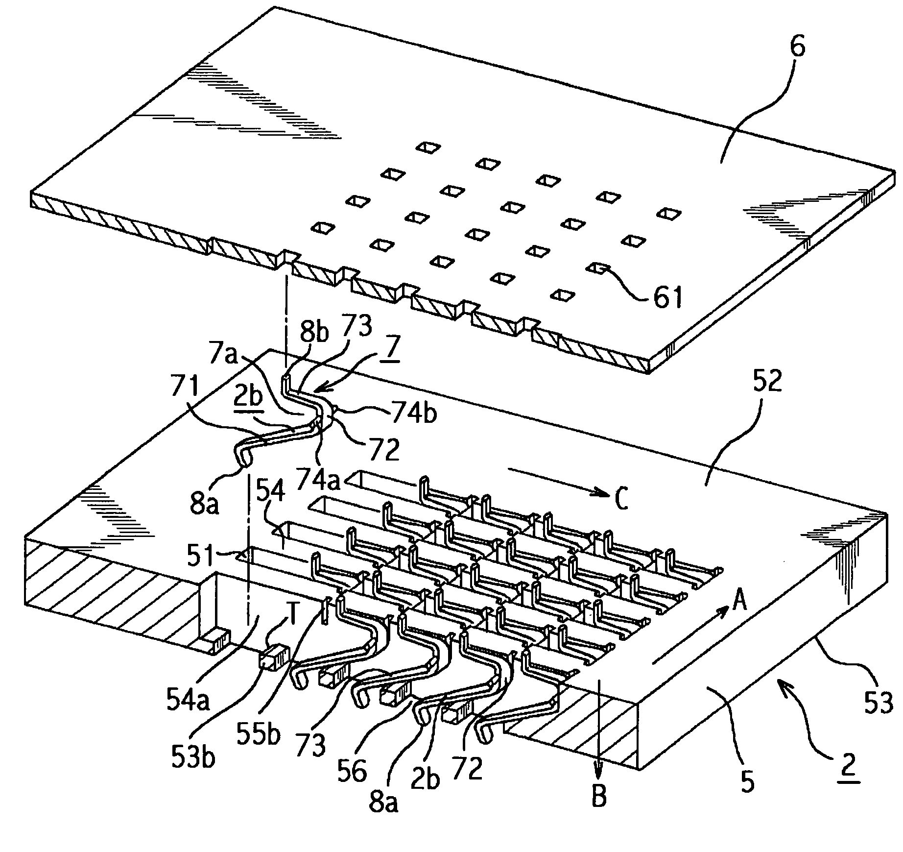
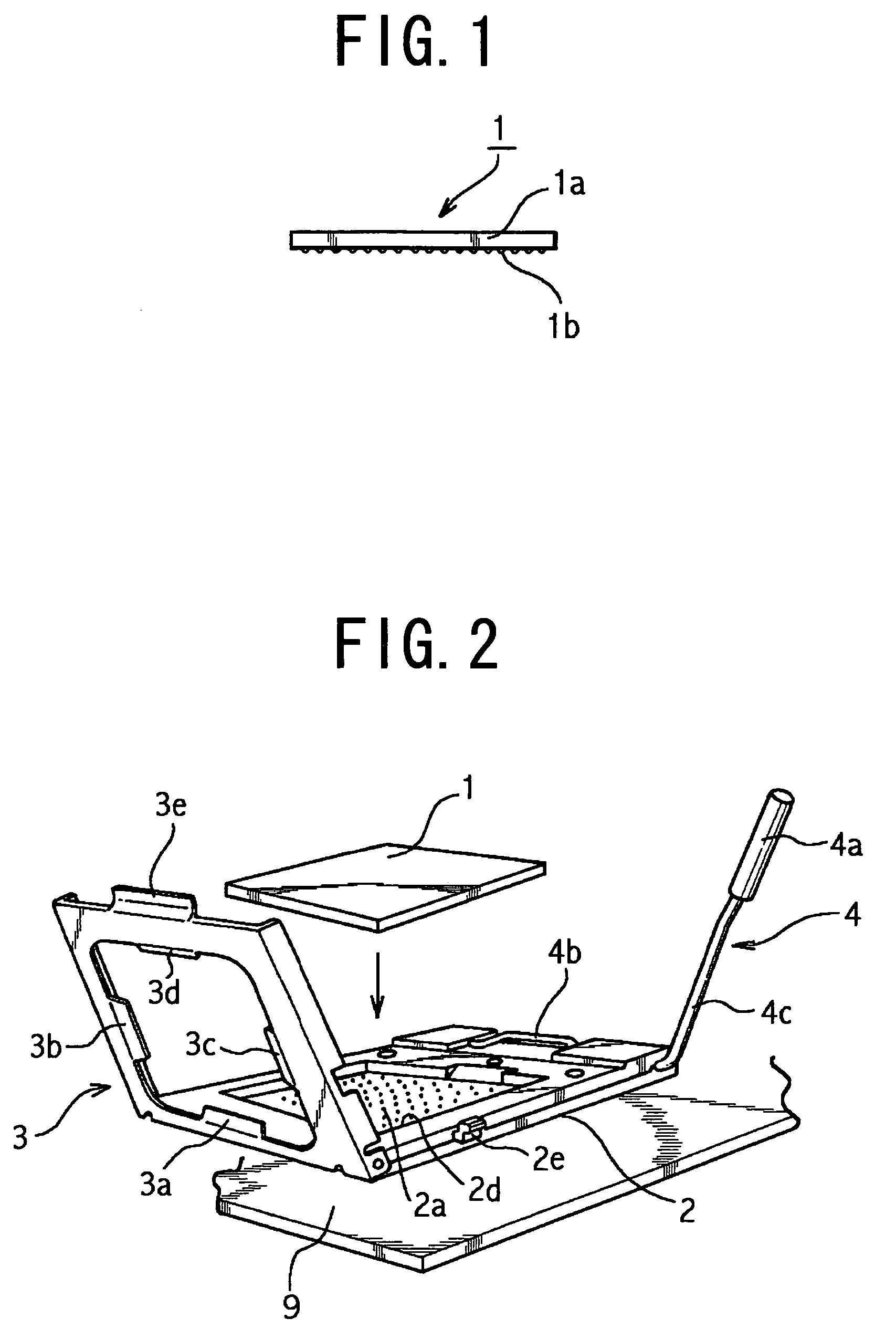
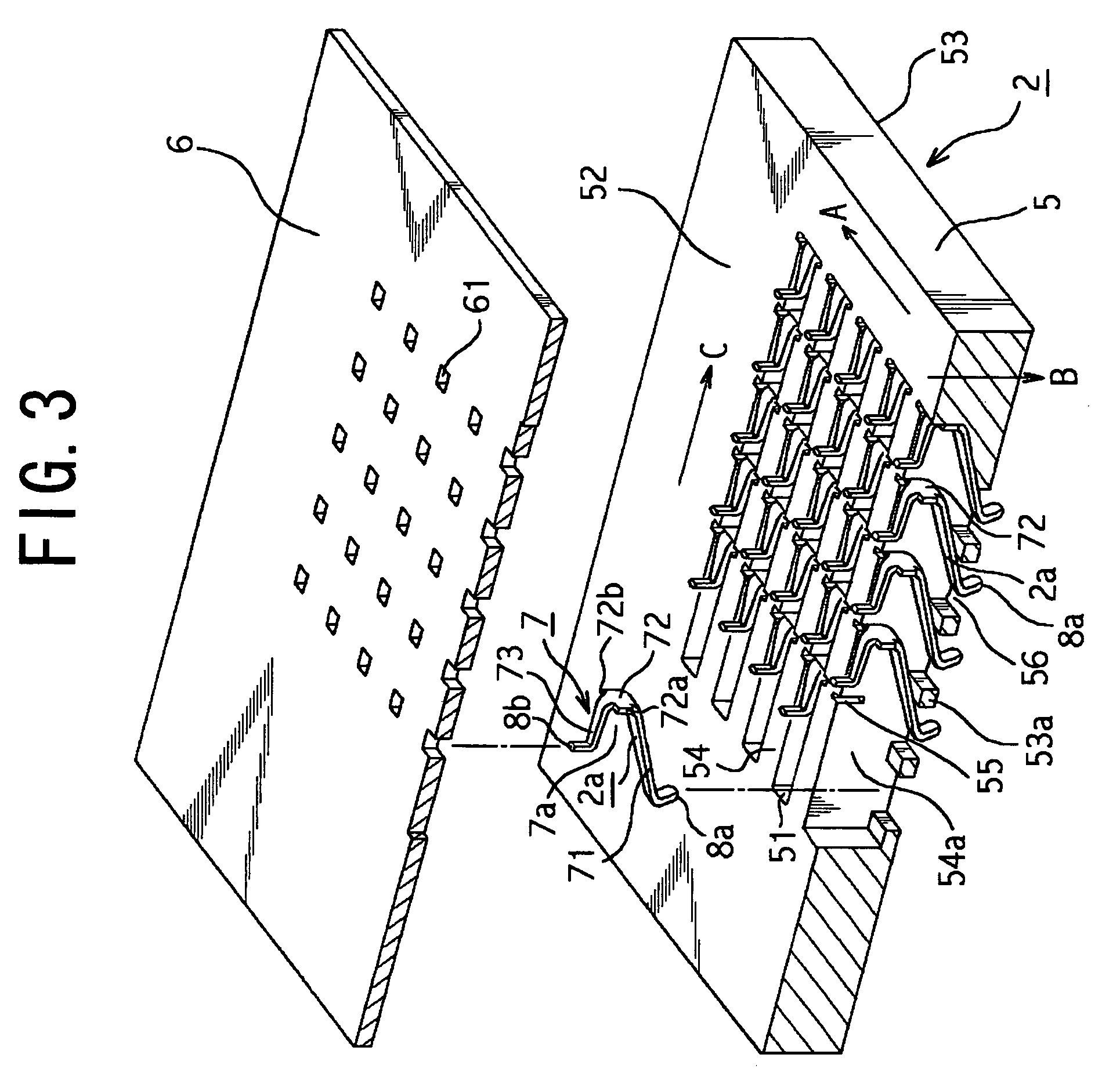
[0045]In the first embodiment, as shown in FIG. 6, the lengthwise dimension L1 of the obliquely extending second straight leg portion 73 is nearly double the lengthwise dimension L2 of the first straight leg portion 71. Thus, the electrical contact (hereinbelow, termed “first electrical contact portion”) P1 between the first contact 8a and the electrode terminal 1b of the electronic component 1 is at an oblique angle and a second electrical contact portion P2 is established between the second contact 8b and the terminal 9a of the printed circuit board 9. A vertical line V1 which passes through the first electrical contact portion P1 is spaced a predetermined distance L3 (about 0.5 mm) in the lengthwise direction C from a vertical line V2 which passes through the second electrical contact portion P2.

[0046]Next, a method for electrically connecting the terminals 1b of the electronic component 1 and the terminals 9a of the printed circuit board 9, through the electrode members 2a, will...

third embodiment

[0056]the present invention will now be described with reference to FIGS. 12, 13 and 14A–14C. Throughout these figures, the same reference numerals and signs are assigned to features which are the same as in FIG. 3–FIG. 11C.

[0057]Referring to FIG. 12, in the third embodiment hole surrounding portions 53b each have a taper T similar to the hole surrounding portions 53b of the flat plate member 5 shown in FIG. 9 but have an electrode member 2c as shown in FIG. 13 instead of the electrode member 2a shown in FIG. 4.

[0058]In the third embodiment, as shown in FIG. 12, the opposing sidewalls 54a of each recess 51 of the flat plate member 5 are formed with pairs of engagement grooves (hereinbelow, termed “second engagement grooves”) 55c each of which is longer than the first engagement groove 55 (refer to FIG. 3), i.e., nearly equal to the depthwise dimension of the recess 51). As shown in FIG. 13, on both sides of the coupling portion 72 of leaf spring 7 are second engagement sections cons...


PUM


Abstract

In a connector board (socket) for an electronic component, each electrode member is a leaf spring formed by bending a conductive plate into a substantially U-shape with an opening facing substantially parallel to a surface of the connector board. A first contact is unitary with one free end of the leaf spring and is held in electrical contact with a corresponding terminal of electronic component, and a second contact is unitary with the other free end of the leaf spring and is held in electrical contact with a corresponding terminal of a printed circuit board. The leaf spring includes a first leg which extends substantially in parallel with a surface of the connector board, a coupling portion which is unitary with the first leg, and a second leg which is unitary with the coupling portion so as to oppose the first leg and which extends obliquely toward a surface of the connector board. Engagement elements are seated within grooves provided in partition walls and are formed unitarily with the coupling portion.

Description

BACKGROUND OF THE INVENTION[0001]1. Field of the Invention[0002]The present invention relates to a connector board for connecting an electronic component to a printed circuit board. More particularly, it relates to a connector board (or “socket”) which is so designed that, when the electronic component of a CPO, an MPU or the like is pushed against it, the electrode terminals of the electronic component and those of a printed circuit board can be electrically connected through electrode portions disposed in the connector board.[0003]2. Description of the Related Art[0004]One known type of connector board for an electronic component is so constructed that, when the electronic component is pushed against the connector board, the electrical contact between the electrode terminals of the electronic component and the electrode portions of the connector board is maintained, while the electrode portions of the connector board are connected to the electrode terminals of a printed circuit bo...

Claims


Application Information

Patent Timeline
Patent Type & Authority Patents(United States)
IPC IPC(8): H01R12/00H01L23/32H01R13/11H01R13/24H01R13/428H01R33/76
CPCH01R13/2435H01R9/096H01R12/52
Inventor MOTOHASHI, SENTARO
Owner TNG CORP LTD
Why Eureka
Try Eureka