Surgical tool having electrocautery energy supply conductor with inhibited current leakage

a technology of energy supply conductor and surgical tool, which is applied in the field of surgical instruments or tools, can solve the problems of limited current leakage between the shaft and the patient, limited current current conductance, and capacitive coupling, and achieves the effects of improving dielectric resistance, low cost, and facilitating manufacturability

Inactive Publication Date: 2006-08-01
INTUITIVE SURGICAL OPERATIONS INC
View PDF28 Cites 1389 Cited by
  • Summary
  • Abstract
  • Description
  • Claims
  • Application Information

AI Technical Summary

Benefits of technology

[0018]The insulation tube will generally comprise a hypotube, typically a hollow tube, having a cross-sectionally circular profile. The insulation tube will generally be dimensioned to have an outer diameter in the range from about 1 / 32 inch to about 3 / 16 inch, preferably from about 1 / 16 inch to about 3 / 16 inch, more preferably having a diameter of about ⅛ inch, and a length in the range from about 12 inches to about 18 inches. Suitable materials for the insulation tube include non-conductive materials such as fluorinated ethylene propylene, polyimide, silicone, polytetrafluoroethylene, tetrafluoroethylene, perfluoroalkoxy, ethylene tetrafluoroethylene, polypropylene, or a combination thereof. Fluorinated ethylene propylene is a preferred material for its low cost and ease of manufacturability. Polyimide is also another preferred material, especially when the separation comprises air, as it further increases dielectric resistance. Polyimide is also a thin material (so as to maximize the radial separation distance) that still provides sufficient stiffness, is sleek so as to not cause any friction with other cables housed within the shaft, and allows for the adhesion of sealants, as described in more detail below.
[0019]The sealed insulation tube may further comprise seals, such as o-rings, heat shrink seals, and the like, located between proximal and distal ends of the insulation tube and the conductor. The seals advantageously center the conductor within the insulation tube and thereby maximize the radial separation distance of the conductor from the insulation tube, particularly when the separation comprises air. The seals may be separate components or be formed integrally with the insulation tube. The seal preferably comprise two pairs of o-rings, a first pair positionable at a proximal end of the insulation tube and a second pair positionable at a distal end of the insulation tube. The sealed insulation tube will typically have a pressure threshold in the range from about −15 psi to 30 psi for resisting fluid leakage as well as bursting during sterilization or cleaning i.e., autoclaving, of the instrument. Further, the sealed insulation tube may comprise an o-ring or heat shrink seal positionable at a center of the insulation tube to further help center the conductor within the insulation tube as well as prevent crimping, slacking, or bending of the conductor.
[0020]The surgical instrument may further comprise a second insulative tubing disposed over the conductor and extending at least within a length of the sealed insulation tube. Suitable materials for the second tubing include non-conductive materials such as fluorinated ethylene propylene, polyimide, silicone, polytetrafluoroethylene, tetrafluoroethylene, perfluoroalkoxy, ethylene tetrafluoroethylene, polypropylene, or a combination thereof. In some instances, the second tubing may extend within an entire length of the sealed insulation tube so as to form a dual insulation tube assembly. Seals may additionally be positionable between proximal and distal ends of the second tubing and the conductor and / or the second tubing and the insulation tube. The second tubing helps prevent bending or slacking of the conductor as well as helps to maintain the conductor within the center of the insulation tube. Moreover, the second tubing may provide extra security for securing the conductor to the sealing mechanisms. Additionally, the non-conductive material forming the second tubing may further enhance the dielectric resistance of the insulation tube and separation.
[0021]The conduction assembly described above advantageously provides electrosurgical treatment in a safe effective manner that minimizes current leakage. The present invention further incorporates additional safety features to further prevent current leakage to non-target tissue so at reduce unwanted and unintended burning of the patient, collateral tissue damage, or the like. In particular, an insulative sheath may be disposed over the conductor. It will be appreciated that such a thin insulative sheath or jacket is sufficient to effectively inhibit DC current, but is not sufficient in and of itself to substantially reduce RF current leakage due to capacitive coupling. Additionally or alternatively, the elongate shaft may be covered with an insulating material.

Problems solved by technology

As such, conduction of the current is limited at a tip of the end effector to the treatment tissue.
Moreover, a reduction in capacitive coupling may result in the current leakage between the shaft and the patient to be limited to a range from about 20 mA to about 35 mA.

Method used


Image

  • Surgical tool having electrocautery energy supply conductor with inhibited current leakage
  • Surgical tool having electrocautery energy supply conductor with inhibited current leakage
  • Surgical tool having electrocautery energy supply conductor with inhibited current leakage

Examples


Embodiment Construction

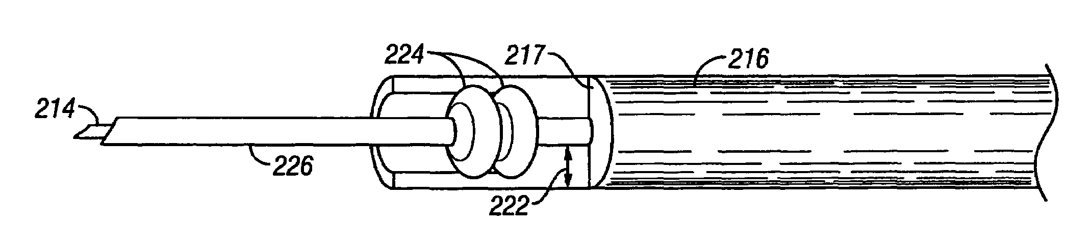
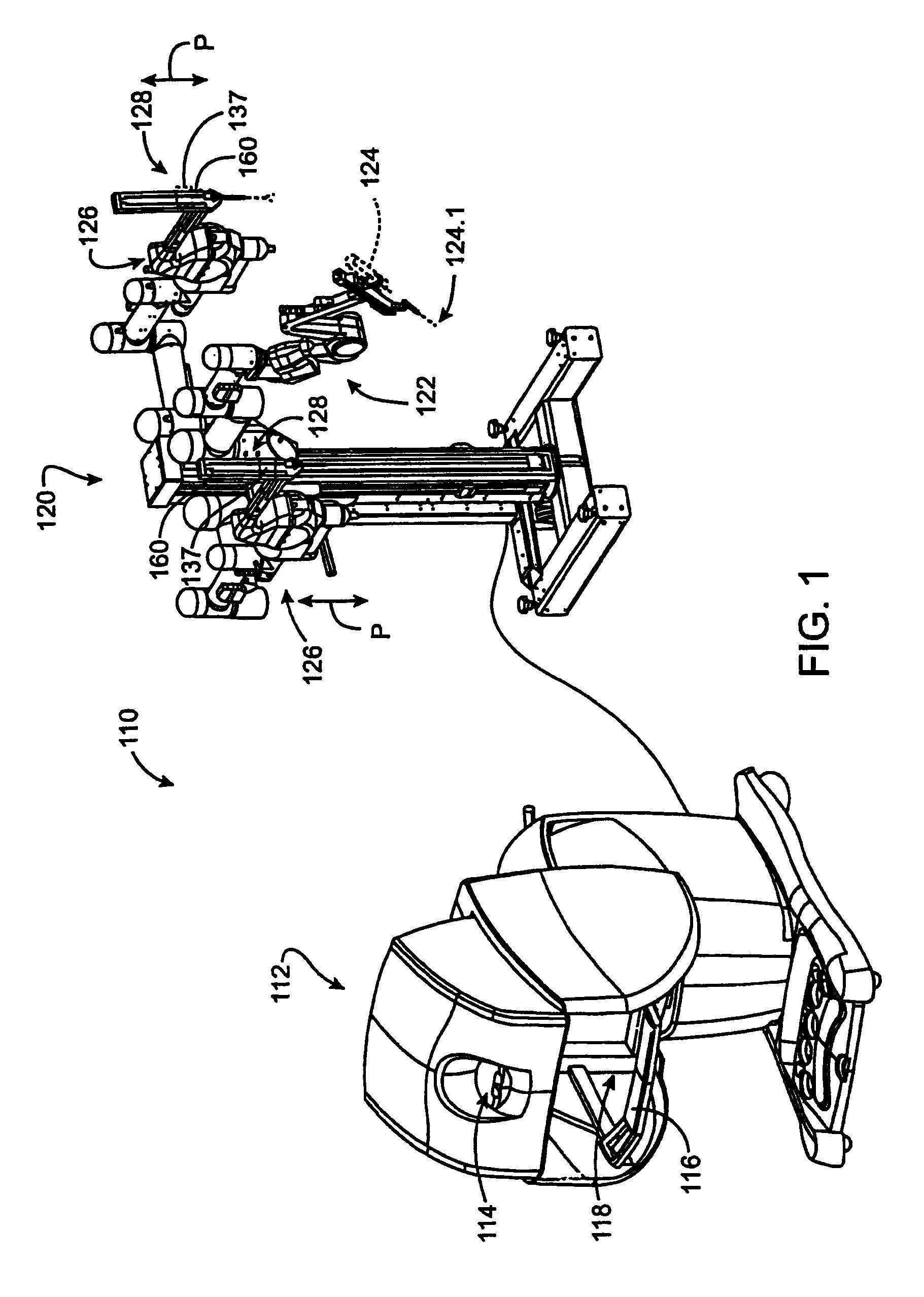
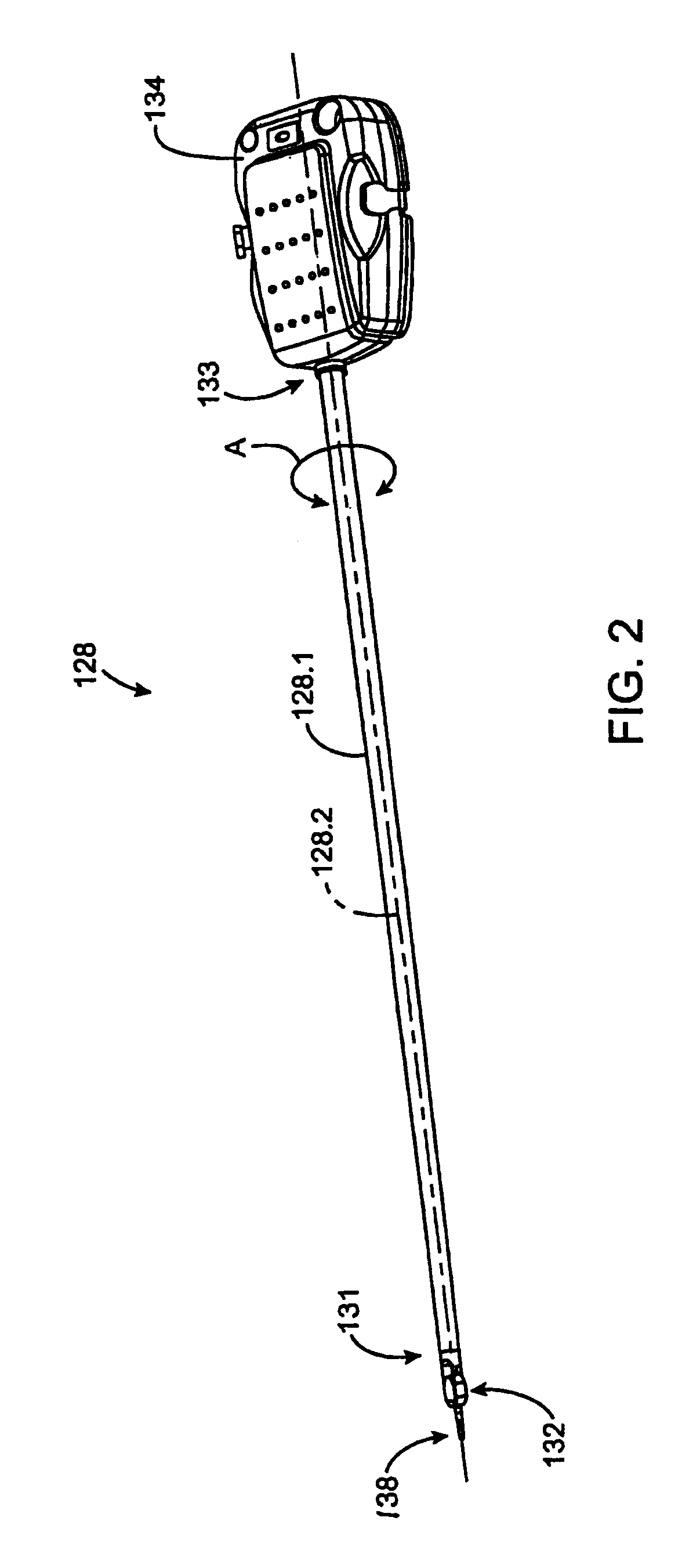
[0037]The present invention provides apparatus, systems, and methods for use in robotically controlled minimally invasive surgical operations. In particular, the present invention relates to improved electrosurgical instruments and systems having electrocautery energy supply conductors that provide inhibited current leakage and methods of performing a minimally invasive surgical procedure while preventing unintended capacitive coupling. Such electrosurgical instruments, systems, and methods also inhibit wrist surface conduction. The conduction assembly advantageously provides electrosurgical treatment in a safe and effective manner by incorporating a variety of safety features to prevent current leakage so as to reduce unwanted and unintended burning of the patient, collateral tissue damage, melting of the instrument, damage to the robotic surgical system, or the like.

[0038]Generally, the electrosurgical instruments of the present invention are capable of treating tissue of an organ...


PUM


Abstract

The present invention provides improved electrosurgical instruments and systems having electrocautery energy supply conductors that provide inhibited current leakage and methods of performing a robotically controlled minimally invasive surgical procedure while preventing unintended capacitive coupling. A surgical instrument generally comprises an elongate shaft having a proximal end and a distal end and defining an internal longitudinally extending passage. An electrocautery end effector is coupled to or disposed at the distal end of the shaft. An interface or tool base is coupled to or disposed at the proximal end of the shaft and removably connectable to the robotic surgical system. Typically, an independent electrical conductor extends from the interface to the end effector to transmit electrical energy to tissue engaged by the end effector. A sealed insulation tube extends within the passage and over the conductor. A separation is maintained between the sealed insulation tube and the conductor.

Description

CROSS-REFERENCES TO RELATED APPLICATIONS[0001]This is application is related to the following patents and patent applications, the full disclosures of which are incorporated herein by reference: U.S. patent application Ser. No. 10 / 726,795; U.S. patent application No. 60 / 431,636, entitled “Flexible Wrist for Surgical Tool”, filed on Dec. 6, 2002; U.S. patent application Ser. No. 10 / 126,451, entitled “Robotic Tool With Monopolar Electro-Surgical Scissors”, filed on Apr. 18, 2002; U.S. patent application Ser. No. 10 / 187,248, entitled “Surgical Tool Having Positively Positionable Tendon-Actuated Multi-Disk Wrist Joint”, filed on Jun. 28, 2002; U.S. Pat. No. 6,491,691, entitled “Minimally Invasive Surgical Hook Apparatus And Method For Using Same”, issued Dec. 10, 2002; and U.S. Pat. No. 6,394,998, entitled “Surgical Tools For Use In Minimally Invasive Telesurgical Applications”, issued May 28, 2002.BACKGROUND OF THE INVENTION[0002]The present invention is generally directed to surgical ...

Claims


Application Information

Patent Timeline
Patent Type & Authority Patents(United States)
IPC IPC(8): A61B18/12A61B18/14A61B19/00
CPCA61B19/22A61B19/2203A61B18/14A61B2019/2242A61B2019/2223A61B2019/2234A61B2018/1422A61B34/70A61B34/71A61B34/30A61B34/37A61B2034/305
Inventor PETERSON, ALAN W.MANZO, SCOTTMESTAS, FRANKRAMANS, ANDRIS
Owner INTUITIVE SURGICAL OPERATIONS INC
Why Eureka
Try Eureka