Covered stent with encapsulated ends

a stent and end technology, applied in the field of encapsulated ends of stents, can solve the problems of serious liver damage, fatal complications, restenosis of the vessel, etc., and achieve the effect of retaining flexibility and enhancing flexibility

Inactive Publication Date: 2006-08-01
CR BARD INC
View PDF118 Cites 121 Cited by
  • Summary
  • Abstract
  • Description
  • Claims
  • Application Information

AI Technical Summary

Benefits of technology

[0008]The present invention is directed to covered stents wherein flexibility of the stent is retained, despite the use of encapsulation techniques. Encapsulation refers to the lamination of a stent between an inner and an outer layer of a plastic material. Compared to a fully encapsulated stent enhanced flexibility can be achieved by encapsulating limited regions of the stent, while leaving a significant portion of the stent—usually a middle portion—covered by a single layer of the plastic material. In this way the limited encapsulation fixes the plastic covering onto the stent with no need for sutures or similar labor intensive mechanical attachments.

Problems solved by technology

However, stents are generally mesh-like so that endothelial and other tissues can grow through the openings resulting in restenosis of the vessel.
This is partially because PTFE is extremely biocompatible causing little or no immunogenic reaction when placed within the human body.
Such blockage prevents or retards flow of bile into the intestine and can result in serious liver damage.
Because the liver is responsible for removing toxins from the blood stream, is the primary site for the breakdown of circulating blood cells and is also the source of vital blood clotting factors, blockage of the bile duct can lead to fatal complications.
However, such methods are far from ideal and suturing, in particular, is very labor intensive.
However, such a monolithically encapsulated stent may tend to be rather inflexible.

Method used


Image

  • Covered stent with encapsulated ends
  • Covered stent with encapsulated ends
  • Covered stent with encapsulated ends

Examples


example 1

[0037]Two memotherm (shape memory alloy stent, product of Angiomed, Division of C. R. Bard, Inc.) biliary stents (S1 and S2), partially encapsulated according to the present invention, were loaded into a 10 French delivery system used for a standard covered biliary stent. The stents were 10 mm×60 mm. The pulling force necessary to load the stents (the force between the outer sheath and the stent) was measured as follows:

S1=6.3N

S2=3.5N

[0038]In comparison, the loading force for a fully encapsulated stent is approximately 50N. After loading the samples S1 and S2 into a pullback delivery system, both were deployed into a glass biliary duct model placed in a 37° C. water bath. All deployment went smoothly and no significant covering damage was observed. Thus, the partially encapsulated stents could be loaded employing a much-reduced force without being compromised structurally.

example 2

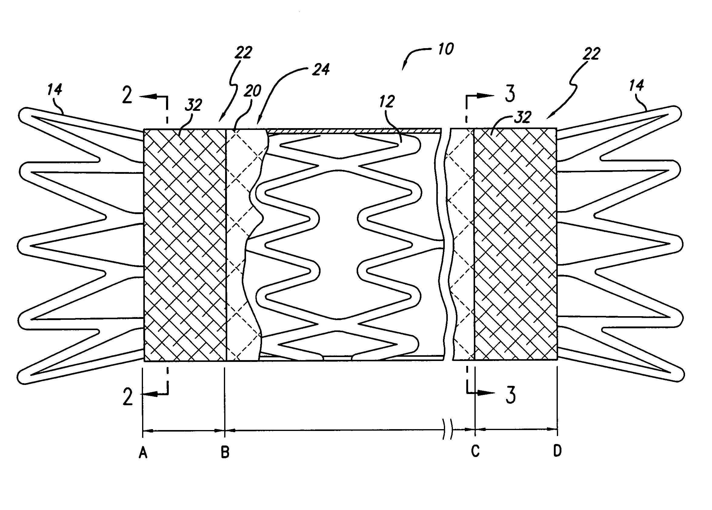
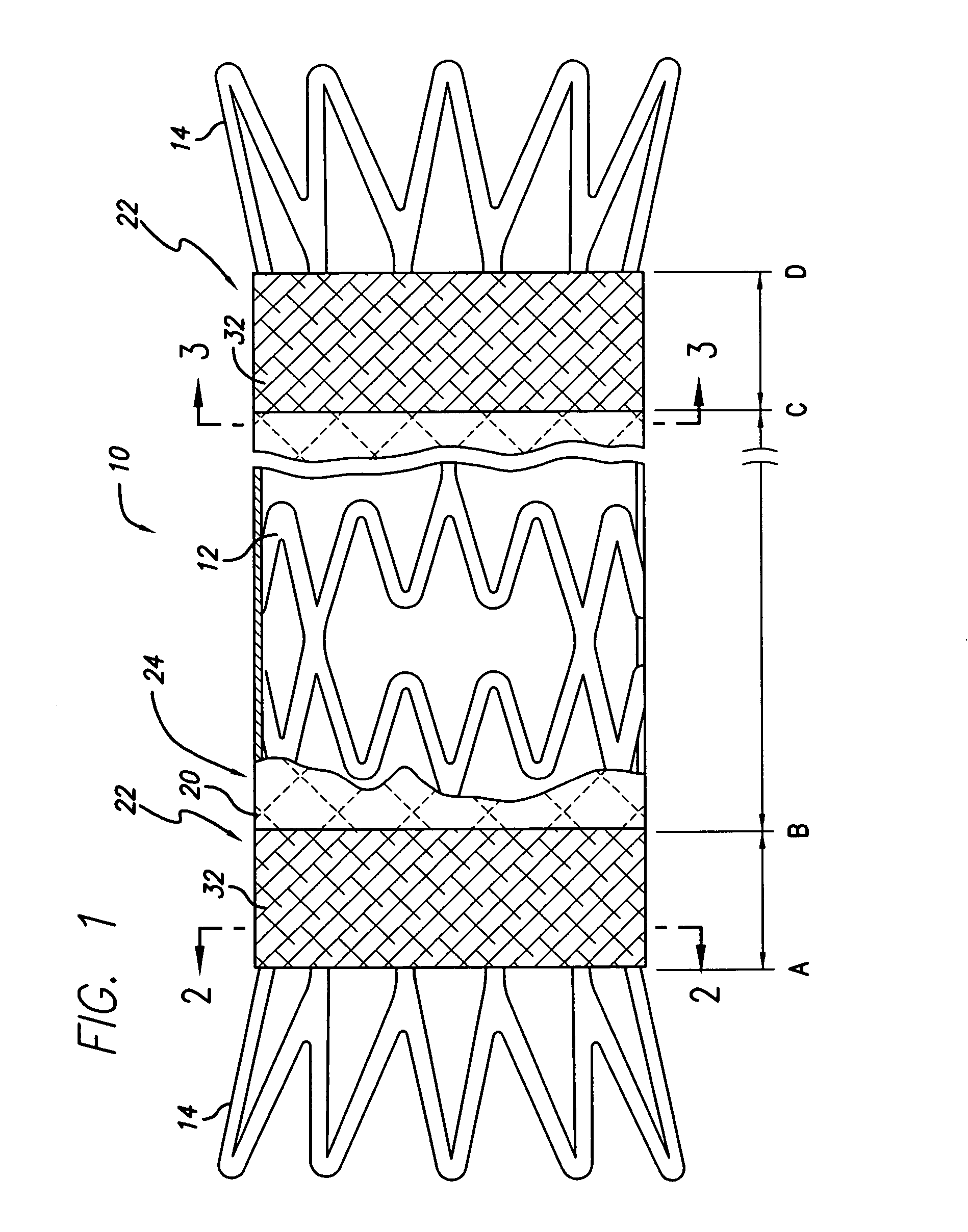
[0039]Three prototypes (P1, P2, and P3) were built using a Gamma 2 (Flexx) design memotherm stent, 12 mm×120 mm. These prototypes were partially encapsulated according to the present invention. More particularly, the abluminal surface of each stent was covered with a tubular ePTFE material, leaving the regions near the stent ends uncovered (to flare outward and anchor the device). The luminal surface near each end of the stent was covered by a 9.95 mm±0.05 mm ring of ePTFE material. The stents were then subjected to heat and pressure so that the overlapping ePTFE material on the luminal and abluminal surfaces was bonded together. The prototypes were then loaded into a 10 French delivery system and were deployed into a glass biliary duct model (45°, 25.4 mm radius) that was placed in a 37° C. water bath.

[0040]The prototypes were loaded according to the standard loading technique used for loading fully encapsulated stents. This loading technique consists of compressing the stents by p...


PUM

PropertyMeasurementUnit
loading forceaaaaaaaaaa
radiusaaaaaaaaaa
diameteraaaaaaaaaa

Abstract

A flexible covered stent having a stent covered on a first surface by a first layer of biocompatible material and on a second surface by both a second and third layer of biocompatible material, the first and second layers and the first and third layers of biocompatible material being bonded to one another through openings in a wall in the stent. The first layer of biocompatible material is longer than both the second and third layers of biocompatible material such that at least a portion of the second surface of the stent is not covered by either second or third layer, imparting flexibility to the stent.

Description

CROSS-REFERENCE TO RELATED APPLICATIONS[0001]This application is a continuation of U.S. patent application Ser. No. 10 / 412,138, filed Apr. 11, 2003, now U.S. Pat. No. 6,740,115 B2, which is a continuation of U.S. patent application Ser. No. 09 / 430,154, filed Oct. 29, 1999, now U.S. Pat. No. 6,579,314 B1, which claims the benefit of U.S. Provisional Application No. 60 / 118,269, filed Feb. 2, 1999, and which is a continuation-in-part of U.S. patent application Ser. No. 08 / 401,871, filed Mar. 10, 1995, now U.S. Pat. No. 6,124,523. The entirety of each of these applications is expressly incorporated by reference as if fully set forth herein.STATEMENT REGARDING FEDERALLY SPONSORED RESEARCH OR DEVELOPMENT[0002]Not applicable.REFERENCE TO A COMPACT DISK APPENDIX[0003]Not applicable.BACKGROUND OF THE INVENTION[0004]Stents and similar endoluminal devices are currently used by medical practitioners to treat tubular body vessels or ducts that become so narrowed (stenosed) that flow of blood or ...

Claims


Application Information

Patent Timeline
Patent Type & Authority Patents(United States)
IPC IPC(8): A61F2/06A61L31/00A61F2/84A61L31/04
CPCA61F2/07A61L31/048C08L27/18A61F2/848A61F2002/072A61F2002/075A61F2/915A61F2230/0054A61F2230/005A61F2/89
Inventor LOMBARDI, SYLVIEKOCH, GUIDOLAYNE, RICHARDEDWIN, TARUN J.SUPPER, WOLFGANGGAMER, WALTERKIRCHHOFF, THOMAS
Owner CR BARD INC
Why Eureka
Try Eureka