
Automatic gain control with analog and digital gain

Inactive Publication Date: 2006-08-01
AVAGO TECH WIRELESS IP SINGAPORE PTE
View PDF6 Cites 34 Cited by
  • Summary
  • Abstract
  • Description
  • Claims
  • Application Information

AI Technical Summary

Benefits of technology

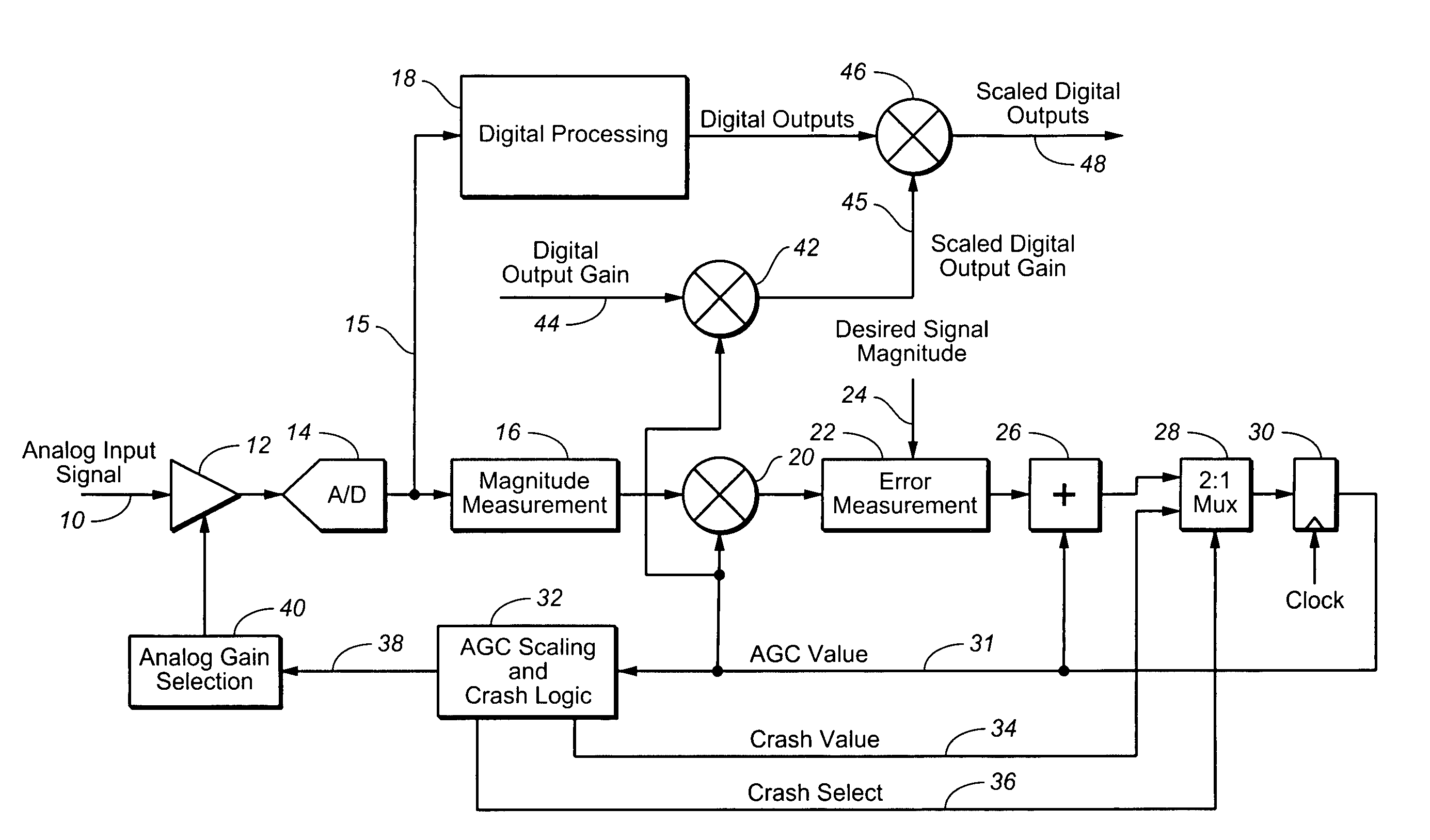
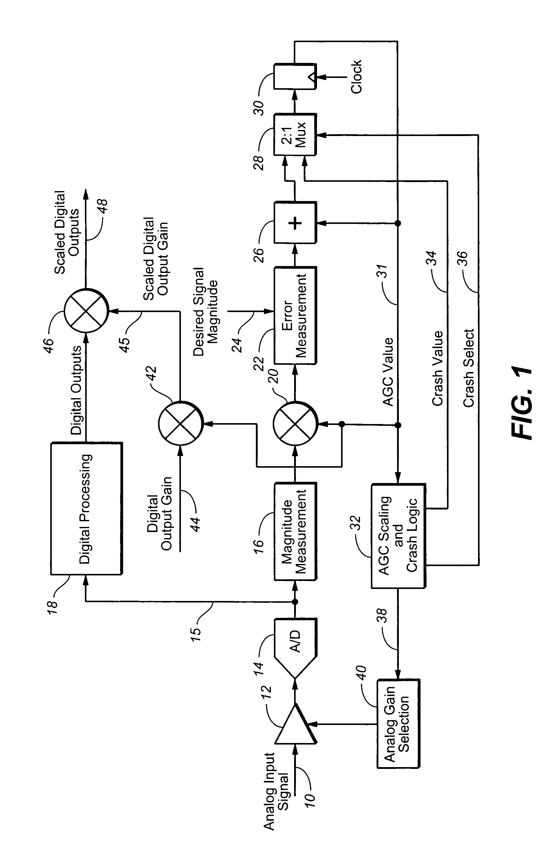
[0006]In accordance with the present invention, an automatic gain control system combines both an analog variable gain amplifier and a digital variable gain stage, both controlled by a common digital gain control system. The analog variable gain amplifier has a relatively small number of gain settings, selected to provide a good signal to noise ratio from an A / D converter, while limiting the board or silicon die area required to implement the gain settings. The controller controls the gain of both the analog and digital variable gain amplifiers. As the overall gain setting crosses over the analog gain settings, the controller changes the analog gain setting. The controller simultaneously changes the digital amplifier gain to maintain smooth transitions between gain levels.

Problems solved by technology

However, the tradeoff is the reduction in signal to noise ratio which results from not using the full operating range of the A / D.

Method used


Image

  • Automatic gain control with analog and digital gain
  • Automatic gain control with analog and digital gain

Examples


Embodiment Construction

[0008]With reference to FIG. 1, there is provided a block diagram of an automatic gain control system according to the present invention. An analog signal is received on an input 10 of an analog gain device 12, e.g. an operational amplifier. The output of amplifier 12 is coupled to the input of an analog to digital, A / D, converter 14. The output 15 of the A / D 14 is coupled to inputs of a magnitude measurement unit 16 and a digital processing section 18. The output of magnitude unit 16 is coupled to one input of a multiplier 20. The output of the multiplier 20 is coupled to one input of an error measurement unit 22. A desired signal magnitude, which may be a stored value, is coupled to a second input 24 of error measurement unit 22. The output of error measurement unit 22 is coupled to one input of an adder 26. The output of adder 26 is coupled to one input of a multiplexor 28. The output of multiplexor 28 is coupled to the input of a register 30. The output 31 of register 30, which ...


PUM


Abstract

An automatic gain control system combining both analog and digital gain units, both controlled by a common digital control system. The overall system gain settings are selected by a combination of analog gain settings and digital gain settings. The number of analog gain settings is less than the total number of system gain settings, so that the board or chip area required for the analog gain settings is reduced, while sufficient range is provided to maintain a good signal to noise ratio from an A / D converter. When a required gain adjustment exceeds one step of the analog gain stage, the system simultaneously adjusts the analog gain and the digital gain unit to provide a smooth transition.

Description

BACKGROUND OF THE INVENTION[0001]The present invention relates to automatic gain control systems and more particularly to a system having both analog and digital gain stages controlled by a digital control system.[0002]Signal transmission systems, e.g. broadcast or cable television systems, generally transmit radio frequency signals over long distances. The signal levels at various receiving locations will vary due to differing transmission distances and various levels of attenuation which may vary from time to time. The receiving systems generally work best if the received signal is at some optimum amplitude level for processing the signals. It is common practice to use automatic gain control, AGC, systems for amplifying received signals to an optimum level for the signal processing systems. An AGC system generally includes a variable gain amplifier and a controller which compares the amplified signal level to a desired level and adjusts the amplifier gain as needed.[0003]While tra...

Claims


Application Information

Patent Timeline
IPC IPC(8): H04L27/08H03G3/00H03G3/30
CPCH03G3/3036
Inventor BURKE, BRADLEY J.RABY, DEAN
Owner AVAGO TECH WIRELESS IP SINGAPORE PTE
Learn More