Method of manufacturing an ink-jet printhead

a technology of inkjet printing and manufacturing method, which is applied in the field of thermal inkjet printing head, can solve the problems of low print speed of printer, ink is unstably ejected, and the productivity of inkjet printing head is reduced, and achieves the effects of high productivity, easy production, and good ejection performan

Inactive Publication Date: 2006-08-08
S PRINTING SOLUTION CO LTD
View PDF5 Cites 19 Cited by
  • Summary
  • Abstract
  • Description
  • Claims
  • Application Information

AI Technical Summary

Benefits of technology

[0015]It is, therefore, an object of the present invention to provide an ink-jet printhead and a method of manufacturing the same, which has good ejection performance as well as high productivity due to the easy production thereof.

Problems solved by technology

However, there is also a disadvantage in that productivity of the ink-jet printhead is reduced.
However, since the ink introducing direction into the ink chamber is vertical to the ink ejecting direction through the nozzle, there is a disadvantage that the ink is unstably ejected.
The low cooling rate of the heater 2 reduces the ejection frequency of the ink and results in the low print speed of the printer.
Further, in the back-shooter type ink-jet printhead, since the heater 2 is formed in the lower portion of the nozzle plate 3, the nozzle plate 3 is prone to be contaminated by the ink sludge.
In addition, in the back-shooter type ink-jet printhead, nevertheless the ink introducing and ejecting directions coincide with each other, it is observed that the ejection of the ink is less stable than in the edge-shooter type or the roof-shooter type ink-jet printhead.

Method used


Image

  • Method of manufacturing an ink-jet printhead
  • Method of manufacturing an ink-jet printhead
  • Method of manufacturing an ink-jet printhead

Examples


Embodiment Construction

[0031]Reference will now be made in detail to the present embodiment of the present invention, examples of which are illustrated in the accompanying drawings, wherein like reference numerals refer to like elements throughout.

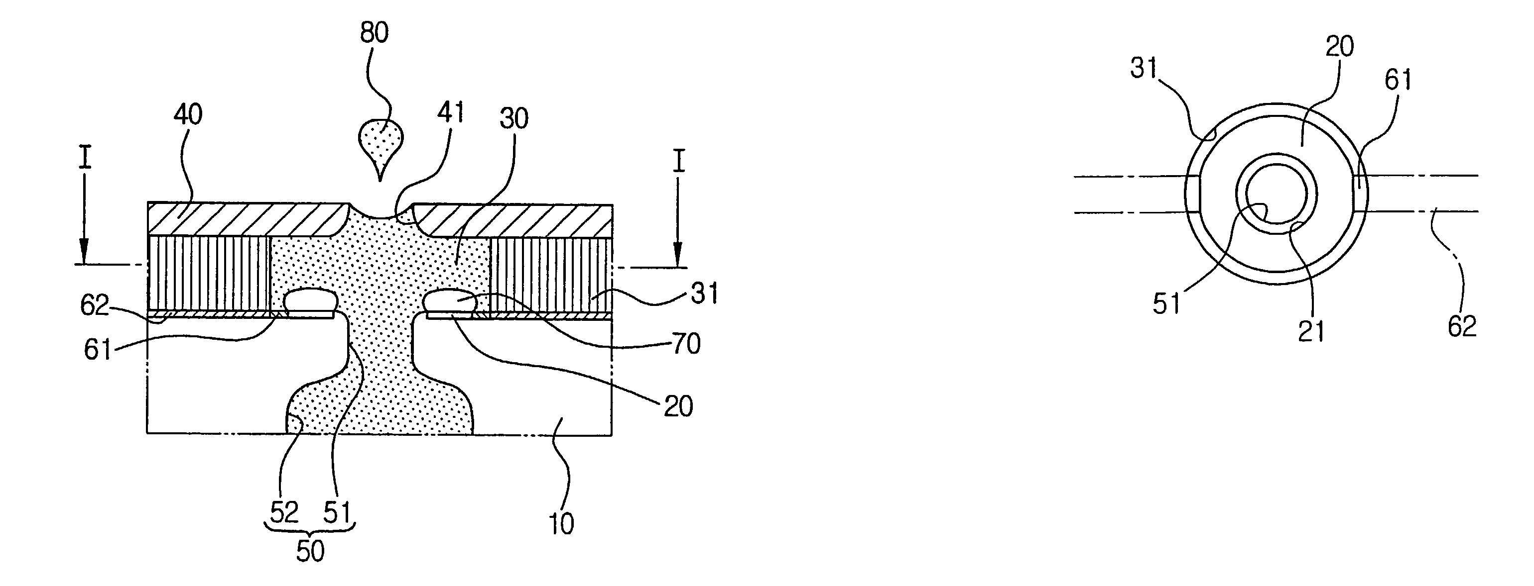
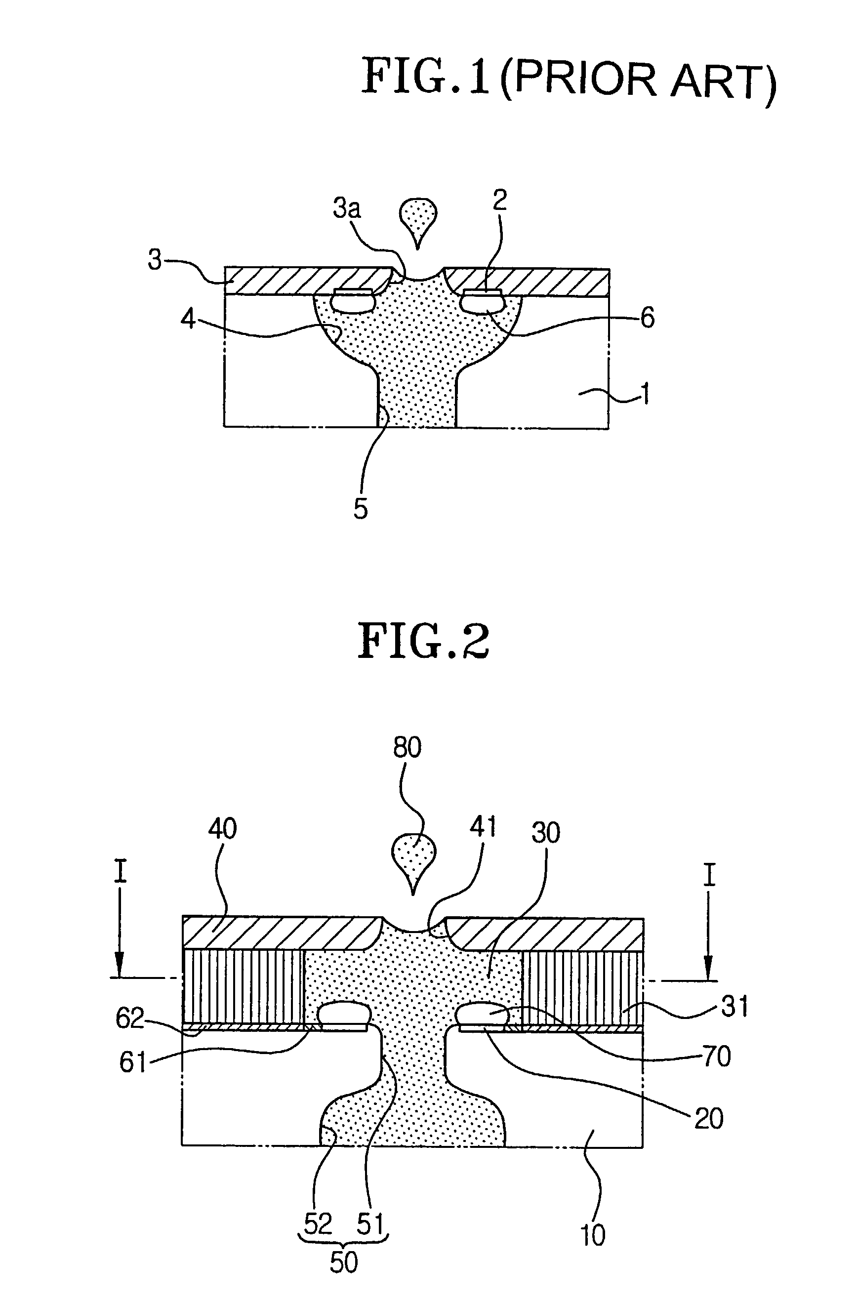
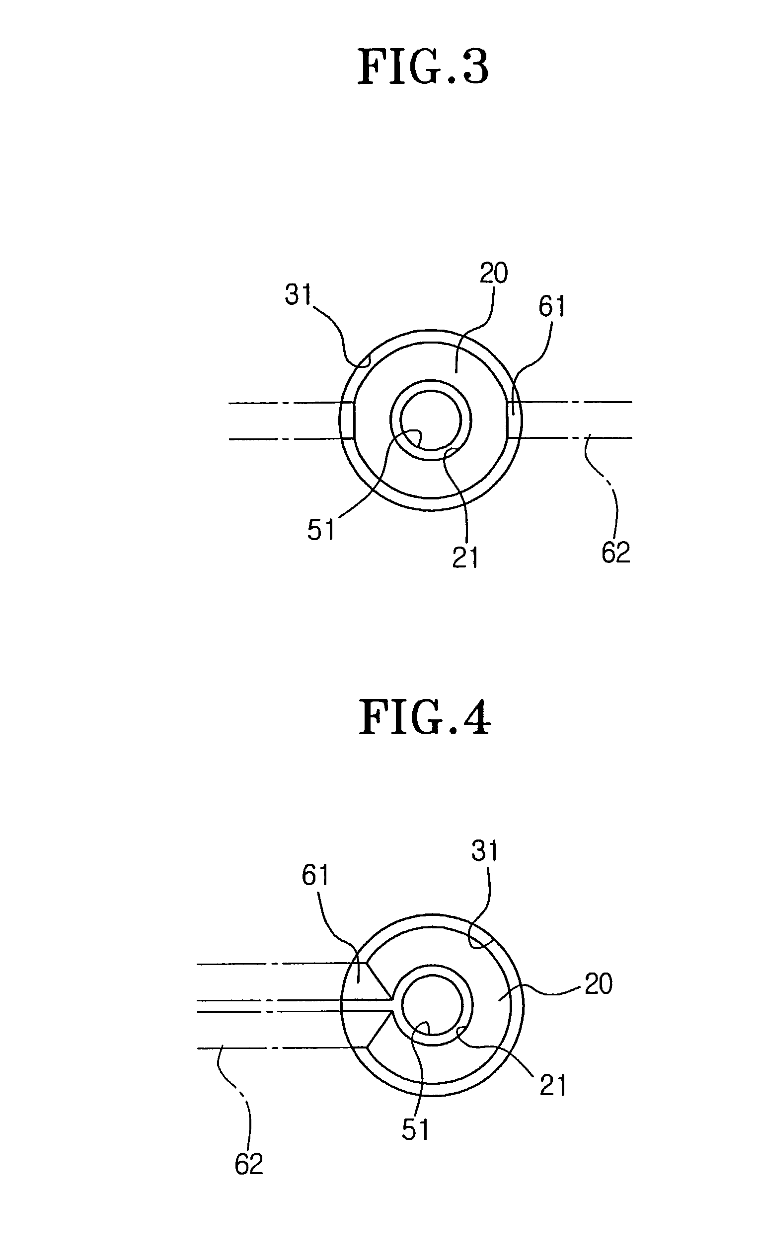
[0032]As shown in FIG. 2, an ink-jet printhead in accordance with an embodiment of the present invention comprises a substrate 10 made of silicone or glass, a heater 20 formed on an upper portion of the substrate 10, an ink chamber 30 disposed above the heater 20, an ink chamber barrier 31 stacked on the substrate 10 to enclose the heater 20 and to form a sidewall of the ink chamber 30, a nozzle plate 40 stacked on the ink chamber barrier 31 and having a nozzle 41, and an ink passage 50 extending through the substrate 10 in a perpendicular direction to a major surface of the heater 20 on which heat is transferred to the ink.

[0033]Although not shown, a driving circuit for actuating the heater 20 is formed on the substrate 10. In order to electrically connect the ...


PUM

PropertyMeasurementUnit
thicknessaaaaaaaaaa
angleaaaaaaaaaa
depthaaaaaaaaaa

Abstract

A method of manufacturing an ink-jet printhead, including forming an insulation film on a substrate, depositing a metal layer onto said insulation film and patterning said metal layer to form a heater, forming an electrical wire on said substrate, etching said substrate at a predetermined depth from a top surface of said substrate in a direction perpendicular to a major surface of said heater to form a narrow passage, depositing an ink chamber barrier layer on said top surface of said substrate and patterning said ink chamber barrier layer to form an ink chamber, stacking a nozzle plate having a nozzle on said ink chamber barrier layer and disposed on an upper portion of said ink chamber barrier layer, and applying predetermined pressure and temperature onto said nozzle plate to bond said nozzle plate and said substrate, and etching said substrate from a bottom surface thereof to form a wide passage communicating with said narrow passage.

Description

CROSS-REFERENCE TO RELATED APPLICATIONS[0001]This application claims the benefit of Korean Application No. 2001-67213 filed Oct. 30, 2001 in the Korean Patent Office, the disclosure of which is incorporated herein by reference.BACKGROUND OF THE INVENTION[0002]1. Field of the Invention[0003]The present invention relates to an ink-jet printhead for use in an ink-jet printer or a facsimile, and more particularly, to a thermal ink-jet printhead.[0004]2. Description of the Related Art[0005]In a general thermal ink-jet printhead, ink filled in an ink chamber is rapidly heated by using a heater to generate a bubble, and a droplet of the ink is ejected onto a print medium by the expansive force of the bubble to form an image on the print medium.[0006]Meanwhile, the thermal ink-jet printhead may be classified into an edge-shooter type ink-jet printhead, a roof-shooter type ink-jet printhead, and a back-shooter type ink-jet printhead according to an ink ejecting method.[0007]In the edge-shoot...

Claims


Application Information

Patent Timeline
Patent Type & Authority Patents(United States)
IPC IPC(8): H05B3/03B21D53/76B41J2/05B41J2/14B41J2/16
CPCB41J2/1404B41J2/14137B41J2/1603B41J2/1623B41J2/1631B41J2/1628Y10T29/49083Y10S29/016Y10T29/49401B41J2/05
Inventor KIM, ILCHO, SEO-HYUN
Owner S PRINTING SOLUTION CO LTD
Why Eureka
Try Eureka