Method and a system for multi-pixel ranging of a scene

a multi-pixel ranging and scene technology, applied in the field of methods and systems for multi-pixel ranging of scenes, can solve the problems of plurality of targets, difficulty in achieving the effect of reducing and rendering such a system impractical, so as to avoid the drastic attenuation of the signal, shorten the length of the fibers, and reduce the weight, cost and volume of the system

Inactive Publication Date: 2006-08-08
ELOP AS
View PDF7 Cites 14 Cited by
  • Summary
  • Abstract
  • Description
  • Claims
  • Application Information

AI Technical Summary

Benefits of technology

[0010]In systems designed to scan targets or scenes having a limited depth, it will make sense to shorten the length of the fibers. The term “depth” as used herein is meant to define the distance from the closest to the furthest point of the viewed target or scene. Such a design can be obtained if only the depth of the scanned scene will be considered, namely, the maximal depth of the scanned scene and not the maximal distance from the system to the scene. Such a design has the advantage of reducing weight, cost and volume of the system, and especially, the avoidance of the drastic attenuation of the signal in the longest fiber. Distance between fibers can be expressed by the formula: Distance=depth of scene / 1.5, wherein 1.5 is the relative speed of light.

Problems solved by technology

The overall length of the fibers, depending on the number of fibers or channels of a specific detector / receiver will be very large, rendering such a system impractical.
This solution may sometimes have substantial limitations, especially due to the attenuation of the signal, which is obtained in the longest fiber, which attenuation can reach even 20 dB.
Despite the fact that the above-described solution seems to be a satisfactory solution, it turned out that it encompasses several problems.
The first and main problem is the situation of a plurality of targets in a field of view, namely, a situation wherein more than one returning pulse echo from a target exists in the defined scene.
In such a situation, the system cannot distinguish between the many returning pulse echoes and is incapable of indicating whether they return through a certain fiber.
Therefore, in such a case, the system will become confused and provide wrong measurements of distances in each of the fibers.
The second problem is the lack of an echo pulse in one of the fibers.
In a situation where there is no echo pulse from the target in one of the fibers, due to a “void” in the target, or due to a very weak echo pulse which is below the preset reception threshold, the system is not capable of identifying the missing echo pulse and assigning it to a certain fiber.
The last problem is time of recovery of the detector / receiver.
In cases where there exists a weak echo pulse in one of the fibers, as compared with the echo pulse of an adjacent one which is much stronger, harm may be caused to the sensitivity of the detector / receiver, so that the weak echo pulse will not be detectable due to the preset reception threshold.
This problem is even amplified when the echo pulse from a certain fiber emanates from the front closer part of the target, while an earlier strong echo pulse stems from the more distant part of the target.

Method used


Image

  • Method and a system for multi-pixel ranging of a scene
  • Method and a system for multi-pixel ranging of a scene
  • Method and a system for multi-pixel ranging of a scene

Examples


Embodiment Construction

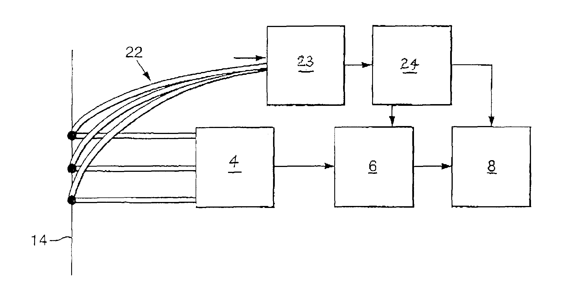
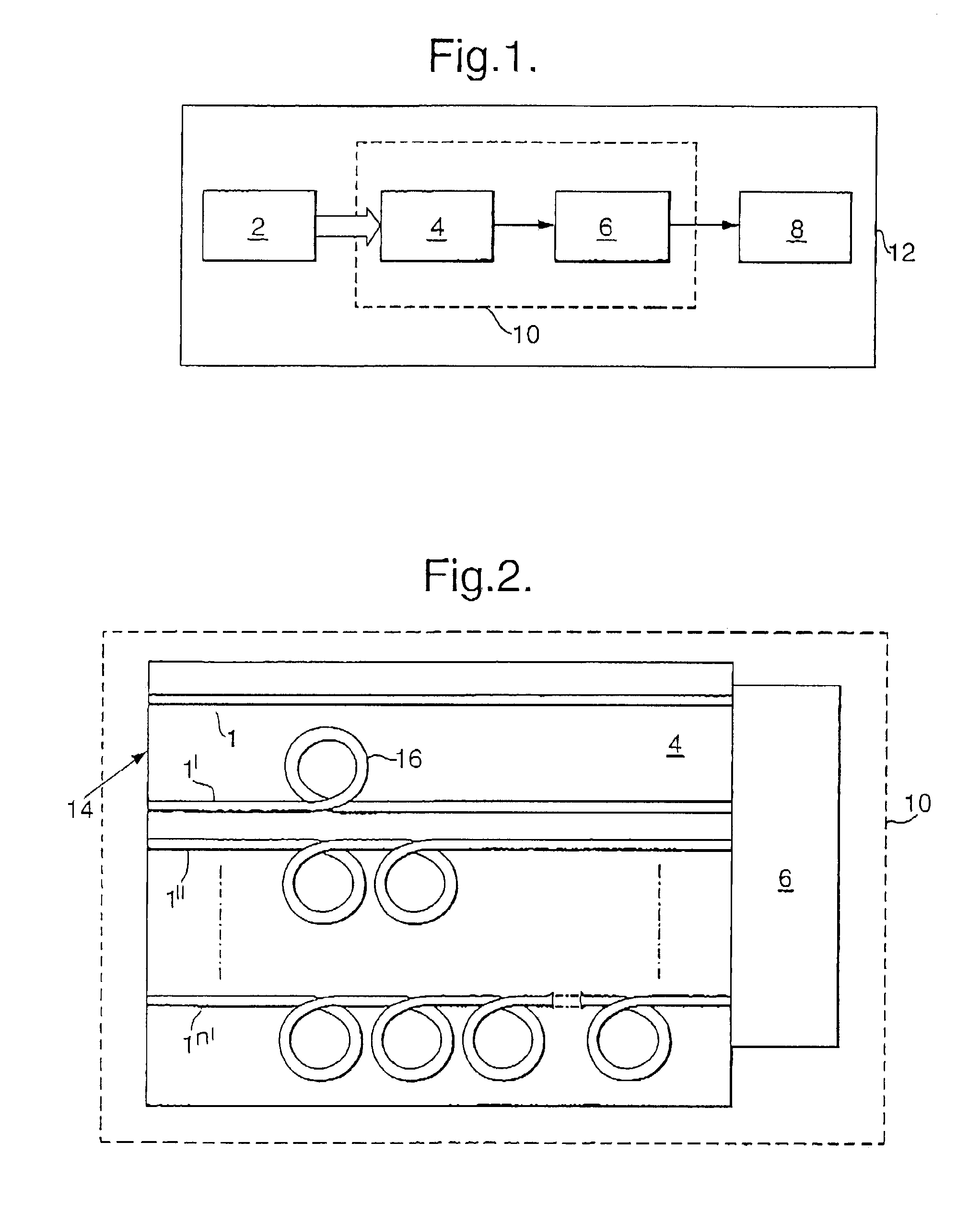
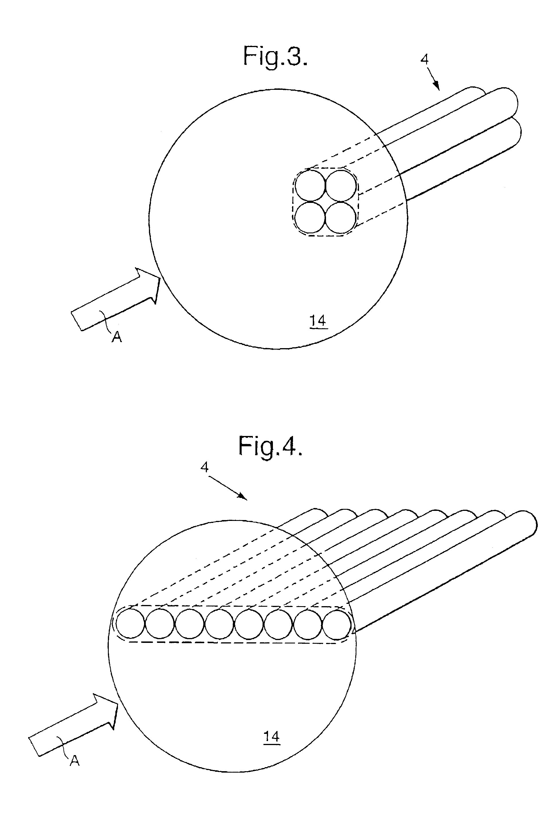
[0036]Referring now to the drawings, there is seen in FIGS. 1 and 2 a block diagram of the system of the present invention, comprising imaging means 2 such as, e.g., a lens, a bundle 4 of optical fibers 1 to 1n′, a single detector / receiver 6 and signal addressing logic 8. The fiber-detector sub-unit is denoted by numeral 10, and the entire system by numeral 12. In FIG. 2 there are seen details of the sub-unit 10 of FIG. 1 also illustrating the working principle of the invention, according to which the whole array of detectors required by conventional range imagers is replaced by a single detector / receiver 6.

[0037]It is assumed that an illuminator (not shown) illuminates the scene by appropriate pulses of light and that a multi-pixel optical image of the scene is produced by imaging means in the ranging plane 14 in which the front end of the fiber bundle 4 is located. The plane 14 collects the echoes of the illuminator light from the various parts of the scene, each having its own ra...


PUM


Abstract

There is provided a method for non-scanning multi-pixel ranging of a scene, comprising the steps of providing a single detector/receiver associated with a time-delay arrangement, producing a time-arrival distribution of pulse echoes of at least part of a remote scene in a defined ranging plane, receiving said distribution as produced on the ranging plane and conveying it, echo pulse by echo pulse through a plurality of echo pulse conveying means to the single detector/receiver, while introducing a time delay, whereby the echo pulses arrive at the single detector/receiver in a sequential order, and using an electronic logic to reconstruct the time-arrival distribution from the time-delayed echo pulses received by the detector/receiver. Systems for ranging of a scene are also provided.

Description

FIELD OF THE INVENTION[0001]The present invention relates to a method and a system for multi-pixel ranging of a scene, using a single detector / receiver associated with a time-delay arrangement and is specifically concerned with such methods and systems in which the time delay is constituted by multi-length optic fibers.BACKGROUND OF THE INVENTION[0002]As far as passive, two-dimensional scanning is concerned, especially in the visible region of the spectrum, present-day technology has provided a satisfactory answer in the form of various detector arrays and matrices, such as, e.g., CCD devices. The problem becomes more complex when the scene to be scanned requires active illumination. Some of the known devices use the direct scanning solution, in which the illuminator beam is passed through a scanning device and impinges upon the scene. The reflected light, after being steered by the same scanner, produces an image on a detector. The moving parts and the required synchronization cons...

Claims


Application Information

Patent Timeline
Patent Type & Authority Patents(United States)
IPC IPC(8): H01J5/16G01C3/08G01S17/89G02B6/06G02B6/28H04N3/10H04N5/225
CPCG02B6/06H04N5/2254H04N3/10G01S17/89G02B6/2861
Inventor ALMI, LUCIENSARID, MOSHE
Owner ELOP AS
Why Eureka
Try Eureka