
Light source using emitting particles to provide visible light

Inactive Publication Date: 2006-08-08
UNIV OF CENT FLORIDA RES FOUND INC +1
View PDF10 Cites 47 Cited by
  • Summary
  • Abstract
  • Description
  • Claims
  • Application Information

AI Technical Summary

Benefits of technology

[0009]The second objective of the present invention is to provide solid state lighting that can use approximately 980 nm laser diodes have an up to approximately 50% or more electrical-to-optical conversion efficiency.
[0010]The third objective of the present invention is to provide solid state lighting having a long-life based on semiconductor lasers.
[0013]The sixth objective of the present invention is to provide solid state lighting that uses upconversion materials that can be easily and inexpensively manufactured.
[0014]The seventh objective of the present invention is to provide solid state lighting that has little waste in the manufacturing process.

Problems solved by technology

However, these traditional light sources have been known to use electrical energy supplies and give off undesirable amounts of heat when being used.

Method used


Image

  • Light source using emitting particles to provide visible light
  • Light source using emitting particles to provide visible light
  • Light source using emitting particles to provide visible light

Examples


embodiment 1

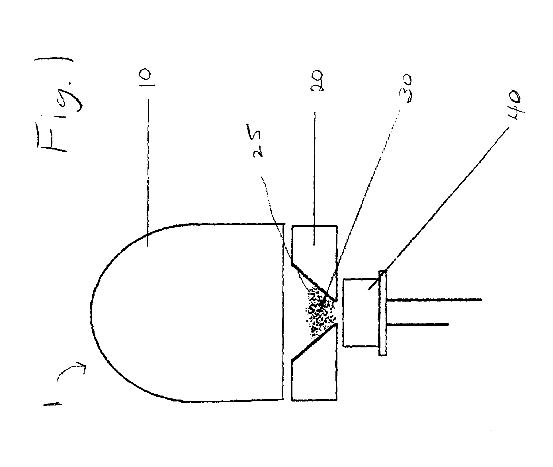
[0036]FIG. 1 shows an upconversion embodiment 1 of the invention with conical reflector 25. An approximately 970 to approximately 980 nm diode laser 40 can be used to pump the upconversion material particles (to be described later) within a mixture 30 of the upconversion particles that are encapsulated in p-PMMA(phosphorylated polymethymethacrylate). The upconversion particles then emit a second wavelength dependant on the type of material used. The light of the second wavelength is then reflected by conical reflector 25 such as an aluminum, metal conical reflector and the like, within sample holder 20 and can be directed towards a lens 10 such as an acrylic lens, polycarbonate lens, and the like. The shape of the lens 10 focuses the light of the second wavelength in a selected beam angle.

embodiment 50

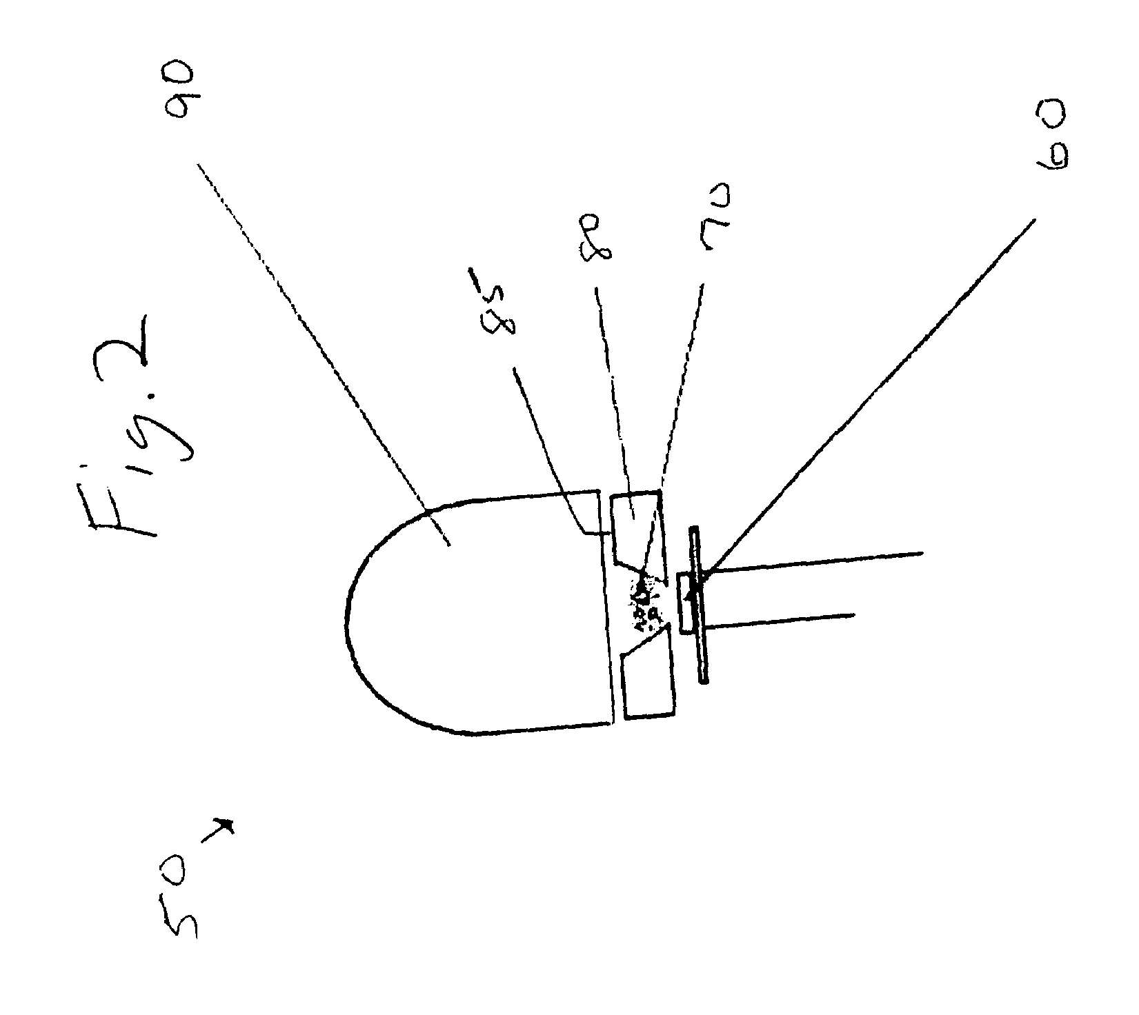
[0037]FIG. 2 shows another upconversion embodiment 50 with a reflector cup 85. An approximately 970 to approximately 980 nm light-emitting diode (LED) 60 can be used to pump the upconversion particles that are part of a mixture 70 of the upconversion particles that are encapsulated in p-PMMA. The upconversion particles then emit a second wavelength dependant on the type of material used. The light of the second wavelength can then be reflected by a reflector cup 85 such as a aluminum, metal reflector cup, and the like, and are directed towards the lens 90 such as an acrylic lens, polycarbonate lens, and the like. Similar to the lens in FIG. 1, the shape of the lens 90 in FIG. 2 can focus the light of the second wavelength in the desired beam angle.

embodiment 100

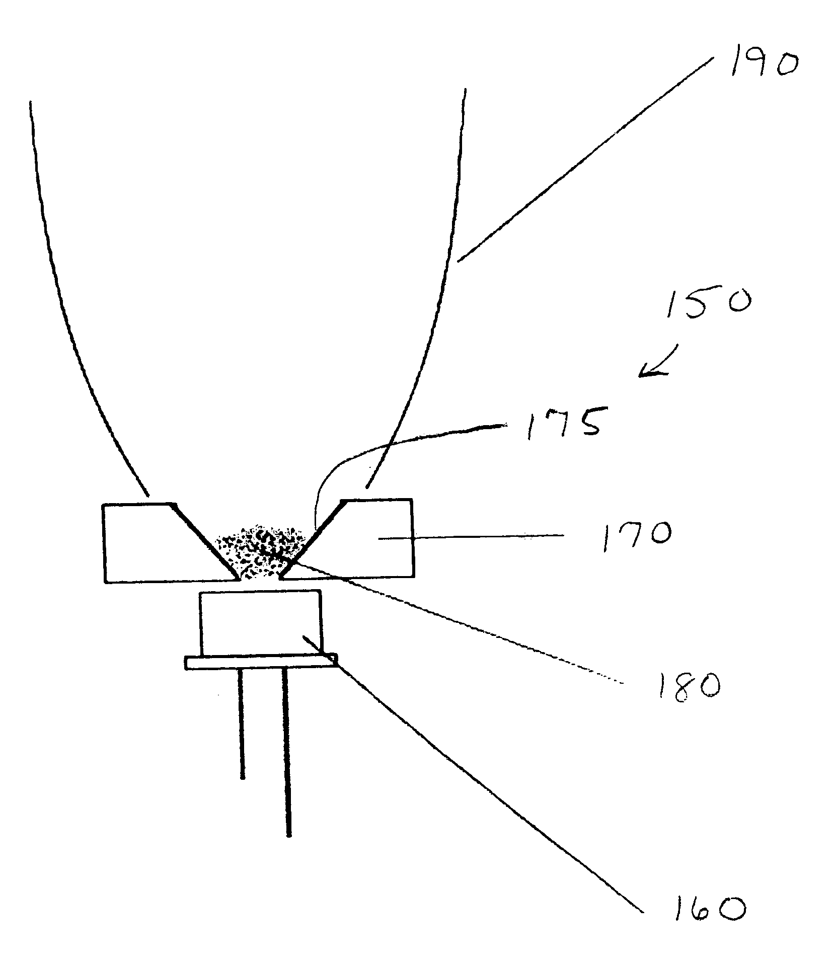
[0038]FIG. 3 shows an embodiment 100 of the output of a diode laser 110 coupled to a waveguide 120. The output of an approximately 970 to approximately 980 nm diode laser 110 can be coupled into a waveguide 120, such as a planer (e.g., flat glass), optical fiber, and the like. The waveguide 120 delivers the near-infrared pump light to the upconversion particles that are in the mixture 140 of the upconversion particles encapsulated in p-PMMA. The upconversion particles then emit a second wavelength dependant on the type of particles used. The light of the second wavelength is then reflected and directed by a reflector 130 such as a parabolic, compound parabolic concentrator (CPC), or reflector cup, and the like.


PUM


Abstract

Upconversion methods and devices that converts near-infrared light to the visible spectrum using a rare-earth-doped crystalline host for use as general and decorative lighting. The pseudo-monochromatic output of the processes can be specified by altering the amount and type of rare-earth material used and by selection of an appropriate host. Using rare-earth materials such as ytterbium-erbium or ytterbium-thulium can produce red, green and blue emissions, where the additive mixture of these colors yields a high-quality white light. The materials can be adjusted to achieve white light with any color temperature and high color-rendering index (CRI) for any general and decorative lighting applications both indoors and outdoors.

Description

[0001]This invention claims the benefit of U.S. Provisional Patent Application 60 / 392,131 filed Jun. 27, 2002.FIELD OF INVENTION[0002]This invention relates to visible light sources, and in particular to methods and devices for forming visible light sources, such as wall and ceiling lights using upconversion of near infrared light with rare earth type particles. This invention relates to U.S. Pat. No. 6,327,074 to Bass et al., by the same assignee as the subject invention, and to U.S. patent application Ser. No. 09 / 919,131 filed Jul. 31, 2001, to Bass et al. by the same assignee of the subject invention which are both incorporated by reference.BACKGROUND AND PRIOR ART[0003]Incandescent and fluorescent light sources have been known to be the most popular sources of visible white light. However, these traditional light sources have been known to use electrical energy supplies and give off undesirable amounts of heat when being used.[0004]The Secretary of Energy, Spencer Abraham, at th...

Claims


Application Information

Patent Timeline
IPC IPC(8): H01J1/62H05B33/00
CPCC09K11/7773F21S48/1394F21V7/22F21S48/1136Y02B20/181F21W2121/00F21Y2101/02H01L33/507F21K9/64F21S41/13F21S41/37F21V7/24F21Y2101/00F21Y2115/30Y02B20/00
Inventor DUCHARME, ALFRED D.BASS, MICHAELRAPAPORT, ALEXANDRA
Owner UNIV OF CENT FLORIDA RES FOUND INC
Learn More