
Folded path flat-plate antennas for satellite communication

a satellite communication and flat-plate antenna technology, applied in the direction of antennas, slot antennas, linear waveguide fed arrays, etc., can solve the problems of high cost, limited low-angle (low elevation) scanning, and vehicle-mounted antenna systems suitable for communication via such satellites

Active Publication Date: 2006-08-08
BAE SYST INFORMATION & ELECTRONICS SYST INTERGRATION INC
View PDF1 Cites 8 Cited by
  • Summary
  • Abstract
  • Description
  • Claims
  • Application Information

AI Technical Summary

Benefits of technology

[0003]Vehicle-mounted antenna systems suitable for communication via such satellites, while the vehicle is in motion, are subject to a number of constraints. The antenna is desirably of relatively small size, low weight and reasonable cost. Thus, while a two-dimensional fully electronically scannable phased-array type antenna might be considered, cost would generally be prohibitive and low angle (low elevation) scanning would typically be limited. Additional constraints are requirements for adequate antenna gain, with wide beamwidth to enhance signal capture, but with low sidelobe performance. Sidelobe performance can be discrimination between signal transmission / reception characteristics (i.e., antenna patterns) of adjacent satellites to avoid interference during signal reception and transmission from a vehicle.

Problems solved by technology

Vehicle-mounted antenna systems suitable for communication via such satellites, while the vehicle is in motion, are subject to a number of constraints.
Thus, while a two-dimensional fully electronically scannable phased-array type antenna might be considered, cost would generally be prohibitive and low angle (low elevation) scanning would typically be limited.
Additional constraints are requirements for adequate antenna gain, with wide beamwidth to enhance signal capture, but with low sidelobe performance.
Generally, known forms of prior antennas have not been capable of meeting all constraints relevant to such usage.

Method used


Image

  • Folded path flat-plate antennas for satellite communication
  • Folded path flat-plate antennas for satellite communication
  • Folded path flat-plate antennas for satellite communication

Examples


Embodiment Construction

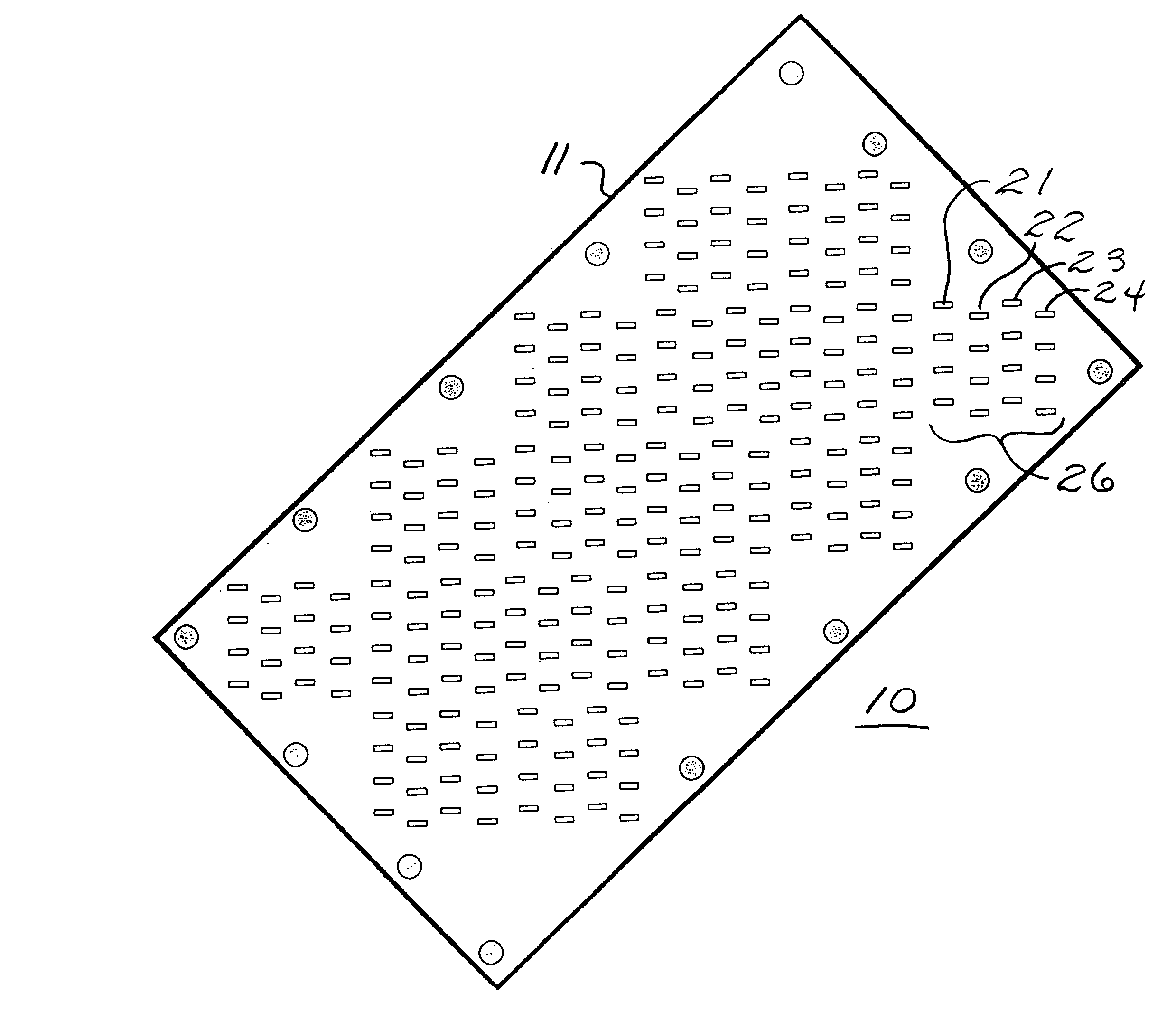
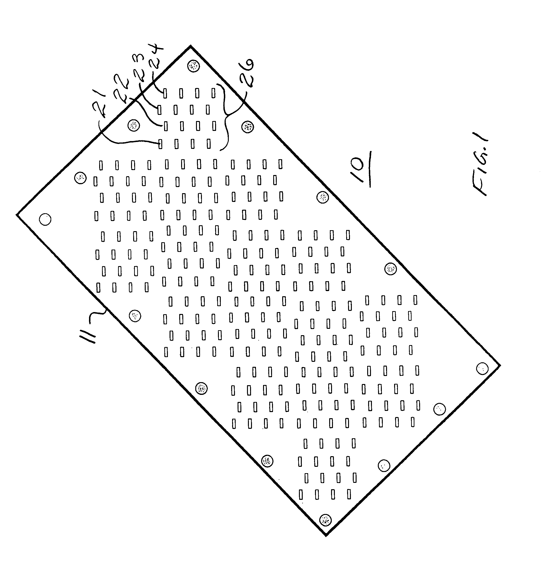
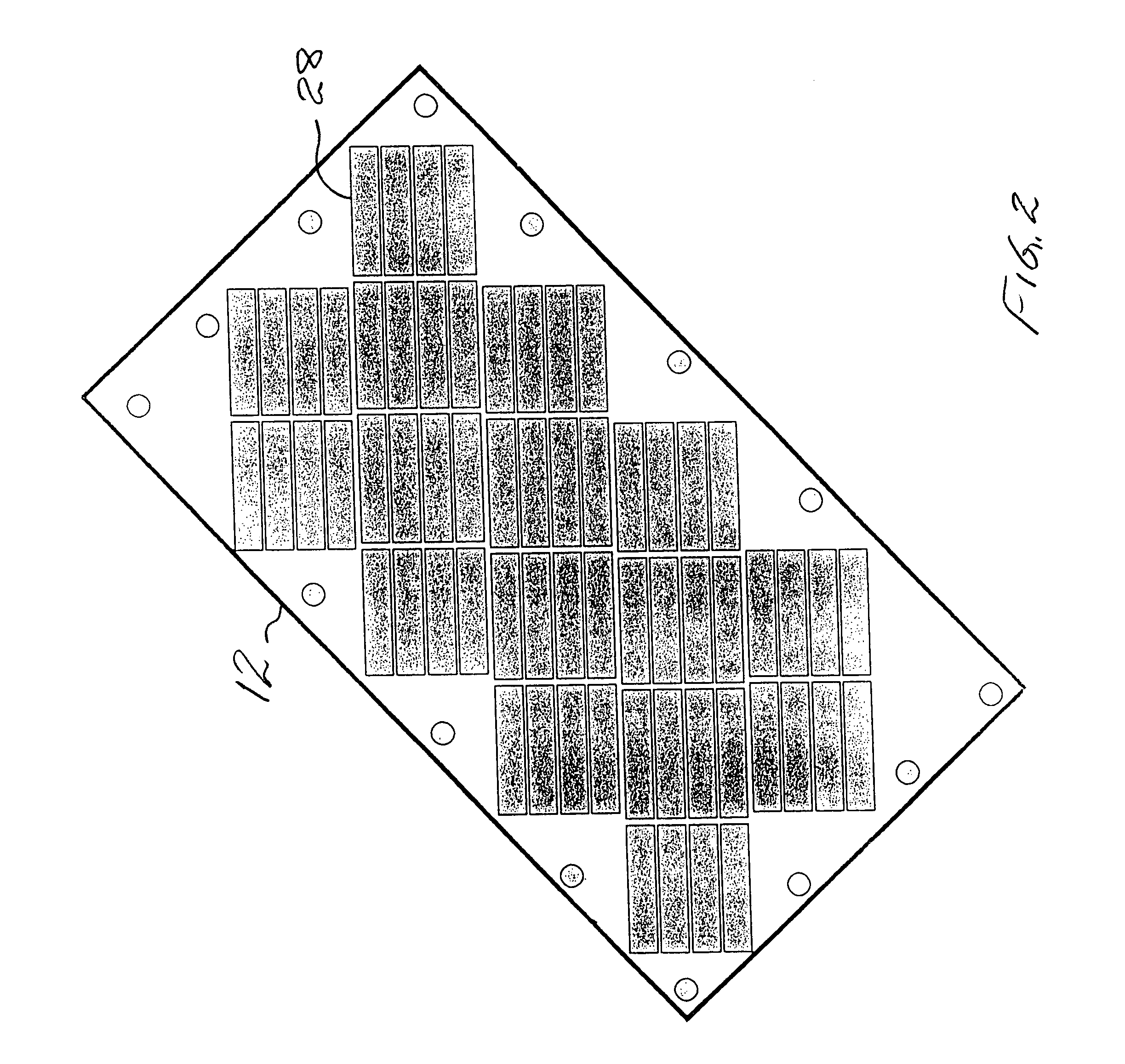
[0050]FIG. 1 is a front or plan view of a flat-plate antenna having 256 slot radiating elements arranged in sixteen sub-arrays and configured for use in an antenna system to provide communication with a moving vehicle via a satellite, such as satellites of a SATCOM system. Length and width dimensions of an example of a FIG. 1 antenna provided for that application may be approximately 15 inches by 5.8 inches. The basic structure of the antenna may comprise a unitary intercoupling network assembled from a stack of nine conductive layers (e.g., aluminum plate or sheet sections) having openings machined or otherwise formed therein. The height or thickness of the entire stack of nine layers may be of the order of one-half inch. As will be discussed, a support layer (e.g., a form of printed circuit board) may be positioned below the bottom layer (i.e., below the ninth layer) to support one or more signal processing units and a signal port (e.g., input / output port).

[0051]In particular appl...


PUM


Abstract

Flat-plate antennas have a compact form by use of a folded path network construction whereby received signals are coupled through a unitary network structure to an adjacent signal processing unit. On a folded path basis, processed signals are then coupled back into the network structure, combined with other received processed signals and then passed out of the network structure to an adjacent signal port. The signal processing unit may provide either amplification, phase shifting, or both. By reciprocal operation a signal to be transmitted may be divided into sub-array components, processed (e.g., power amplified and phase shifted), further divided, and coupled to each slot radiating element (e.g., 256 slots) of an array of slot sub-arrays. The unitary network structure may be formed of a stack of aluminum layers or plates, each having openings formed therein so that when the plates are stacked together normal and transverse waveguide sections are formed internally in an arrangement to provide signal coupling, combining and dividing. Methods employing folded path processing are also disclosed.

Description

[0001]A variety of forms of antennas have been proposed for point-to-point communication via satellite. In such applications, a radio frequency signal is transmitted from a first antenna providing a beam directed at a satellite, the satellite acts as a repeater re-transmitting received signals, and a second antenna directed at the satellite receives a signal replicating the signal as transmitted from the first antenna. The sequence may be reversed to enable reception at the first antenna of a signal representative of a signal transmitted from the second antenna, to provide two-way communication.[0002]In a form of satellite communication system (referred to generally as a SATCOM system), a series of satellites may be maintained in fixed (GEO) synchronous orbit above the equator, with the satellites in spaced positions along an arc within an equatorial plane. The MILSTAR system is an example of such a system. MILSTAR is a military satellite communication system. Its GEO synchronous sa...

Claims


Application Information

Patent Timeline
IPC IPC(8): H01Q13/10
CPCH01Q21/064H01Q21/005
Inventor LACKEY, RAYMOND J.LOPEZ, ALFRED R.
Owner BAE SYST INFORMATION & ELECTRONICS SYST INTERGRATION INC
Learn More